CFA Piling vs. Rotary Bored Piling

CFA PILING

CFA (Continuous Flight Auger) piles are quick to install and they offer an efficient solution for more lightly-loaded structures.

Using our CFA rigs, we can offer the best and most cost-effective solution for our clients’ projects across the UK. Our knowledge and expertise, as well as our experienced site team and on-board technology, means that we can monitor quality and performance real-time.

CFA technology offers the ideal solution for projects in urban locations because it eliminates vibration and disturbance to adjacent structures, and it reduces noise emissions.

Continuous CFA piles are suitable for most soil conditions and construction projects. They are the best and most effective solution when piling is required close to existing buildings, or in built-up areas because this piling approach is virtually vibration free, and it has low noise levels.

CFA Drilling technique: Continuous flight auger piles are constructed rotating an auger string into the ground by injecting concrete under a minimum pressure through the hollow stem of the auger. The soil is replaced with concrete in one continuous movement as the auger is withdrawn. After the pile head is cleared of debris, steel reinforcement is plunged into the pile concrete.

The technique requires no additional ground support, such as casing or drilling fluids, because the bore is self-supporting as the auger is rotated into the ground and the concrete supports the bore after extraction.

Ground conditions: CFA piling is amenable to a broad range of ground conditions from medium dense sands and gravels through to stiff clays and even low grade rock. The technique is not recommended in very soft clays or silts or in very loose sands or gravels.


Advantages of CFA Piling:

  • High production rates mean that piles are commercially attractive
  • Broad range of auger sizes (300mm to 1200mm diameter) means that the most economical use of construction materials is possible
  • Depths of up to 25m means that CFA piling is effective for low to mid-range loading thus suitable for most commercial and residential projects
  • Low noise emissions
  • Virtually vibration free

Sectors: residential, commercial (multi-storey), urban locations


CFA PILE CONSTRUCTION SEQUENCE 

ROTARY BORED PILING

Rotary Bored Piling is carried out by our Large Diameter Piling (LDP) rigs which offer higher power (torque) than our CFA rigs so they are more agile and able to overcome underground obstructions.

When constructing rotary bored piles we have the ability to quickly change coring or digging tools and auger type to best suit soil conditions. We can also install plunge columns in the pile to facilitate top-down construction. Compared with other piling techniques LDP can offer larger load capacities and be installed to far greater depths.

Drilling technique: Rotary bored piles are constructed by rotating a casing into the ground to support poor or granular ground and then removing the pile bore using an auger, bucket or coring unit attached to a telescopic Kelly bar. Once the bore is fully cleaned out to design depth, the pile concrete is tremied into the bore and the casing is extracted leaving a finished pile. Typically, pile reinforcement is cast into the pile during concreting.

Ground conditions: Rotary piling can be employed in almost all ground conditions from soft ground supported by temporary casing through to high grade very strong rock cored in to open-hole techniques.


Advantages of Rotary Bore Piling:

  • Amenable to almost all ground conditions including rock drilling
  • Depths achievable up to 60m with casing and tool diameters up to 1.8m means that very high capacity loads can be achieved
  • Minimal ground disturbance and vibration – resulting risk to adjacent structures and property is limited
  • Simple and efficient installation process
  • Ability to construct sockets into underlying rock
  • Larger diameters feasible
  • Can extend to greater depths when compared with any other piling technique

Sectors: commercial (tower), civils, marine


ROTARY BORED PILE CONSTRUCTION SEQUENCE

Advertisement

Types Of Concrete And Their Strengths

Finding the right type of concrete for your project is essential for getting the best results. Here at EasyMix Concrete we design and supply a huge range of concrete strengths and grades to ensure the ideal solution for any project or application.

Concrete Mixes

Most concrete mix designs use the same type of raw materials: cement, water and aggregate (usually sand and stone), in different ratios. Some types of concrete have additional materials added to give specialist qualities, such as:

  • Fibres – enhanced strength
  • Plasticisers – free flowing, better workability
  • Retarding agents – reduce rate of setting
  • Accelerating chemicals – increase rate of setting
  • Corrosion inhibitors – reduce corrosion of steel rebars 

Have a look through our glossary of concrete types to make sure you get the right concrete for your project. If you’re not sure, or would like to discuss you requirements, simply give the team at EasyMix a call. Even if we can’t supply the exact type of concrete you require, we’ll be more than happy to discuss your project, recommend alternatives and ensure you get the right materials for the best results.

Glossary of Commercial Concrete Types

C7/8 / GEN 0

C7 & 8 concrete mix, Gen 0 concrete or wet lean mix concrete, is commonly used in both commercial and domestic projects for a huge range of general applications, such as kerb bedding, haunching and backing, domestic foundations and blinding.

Ideal for: Cavity filling, kerbing, domestic foundations & haunching.

C10 / GEN 1

C10 concrete, or Gen 1 concrete is an extremely versatile mix used throughout the construction industry for general and housing applications. This includes un-reinforced strip, trench fill and and agricultural applications.

It can also be used for drainage works and blinding house floors, as well as pad foundations and non-structural mass concrete in non-aggressive ground conditions.

Ideal for: Foundations for steps, trench fill, floor blinding & drainage works.

C15 / GEN 2

C15 concrete or Gen 2 concrete is suitable for house floors with no embedded metal. It also provides the ideal material for flooring when no permanent finish or floor covering will be installed, such as carpet or tile.

Ideal for: Foundations for small walls, sheds & conservatories. Paving for steps and paths.

C20 / GEN 3

C20 concrete mix and Gen 3 concrete is commonly used for lightweight domestic applications and foundations, such as driveways and garage, shed & workshop bases. It can also be used to construct internal floor slabs so long as they contain no embedded metal.

Ideal for: Foundations for large walls, garages, houses & extensions. Paving for patios. Reinforced bases & oversites for conservatories, garages, sheds, greenhouses.

C25 / ST 2

C25 standardised mix concrete or ST2 Concrete is widely versatile and used in numerous commercial and domestic projects. It is commonly used for footings and foundations, including mass concrete fill, trench fill and reinforced fill, as well as general groundworks. It can also be used for kerbing, infilling around manholes and small bases for external furniture, such as patios.

Ideal for: Foundations and reinforced bases for houses & extensions. Trench fill, kerbing & patios.

C30 / PAV1 / ST 3

C30 concrete, PAV1 concrete and ST 3 concrete are the most common types of concrete used for pavement construction.

It is also ideal for lighter use external applications, such as slabbing, as well as outdoor paved areas such as stables, driveways, walkways, patios and garages.

PAV 1 mixes have an air entrainment additive to create standard sized air bubbles in the concrete. This helps to protect the surface from freeze-thaw cycles, making it especially useful for outdoor paving.

Ideal for: Paving external kennels and reinforced hard standings. Reinforced bases for workshops and unreinforced bases for houses & extensions.

C35 / PAV2

C35 concrete and PAV2 concrete is a heavy-duty use concrete. It offers high quality similar to PAV1, but is much more substantial making it suitable for commercial and industrial use. Common applications include raft foundations, piling and external slabbing and pacing that will be subject to the constant loading and scraping imposed by industrial vehicles and machinery.

PAV 2 mixes have an air entrainment additive to create standard sized air bubbles in the concrete. This helps to protect the surface from freeze-thaw cycles, making it especially useful for outdoor paving.

Ideal for: Reinforced bases for commercial buildings and agricultural light storage areas.

C40

C40 concrete is a strong commercial grade concrete mix most commonly used in the construction of structural and support beams, footings and foundations, roadworks, and in agricultural use.

Ideal for: Foundations for septic tanks, paving HGV parks and agricultural yards.

DIFFERENCE BETWEEN HOT ROLLED STEEL AND COLD ROLLED STEEL

hot and cold rolledCustomers often ask us about the differences between hot rolled steel and cold rolled steel. There are some fundamental differences between these two types of metal. These differences relate to the ways these metals are processed at the mill, and not the product specification or grade.

Hot Rolled

Hot rolling is a mill process which involves rolling the steel at a high temperature (typically at a temperature over 1700° F), which is above the steel’s recrystallization temperature. When steel is above the recrystallization temperature, it can be shaped and formed easily, and the steel can be made in much larger sizes. Hot rolled steel is typically cheaper than cold rolled steel due to the fact that it is often manufactured without any delays in the process, and therefore the reheating of the steel is not required (as it is with cold rolled). When the steel cools off it will shrink slightly thus giving less control on the size and shape of the finished product when compared to cold rolled.

Uses: Hot rolled products like hot rolled steel bars are used in the welding and construction trades to make railroad tracks and I-beams, for example. Hot rolled steel is used in situations where precise shapes and tolerances are not required.

Cold Rolled

Cold rolled steel is essentially hot rolled steel that has had further processing. The steel is processed further in cold reduction mills, where the material is cooled (at room temperature) followed by annealing and/or tempers rolling. This process will produce steel with closer dimensional tolerances and a wider range of surface finishes. The term Cold Rolled is mistakenly used on all products, when actually the product name refers to the rolling of flat rolled sheet and coil products.

When referring to bar products, the term used is “cold finishing”, which usually consists of cold drawing and/or turning, grinding and polishing. This process results in higher yield points and has four main advantages:

  • Cold drawing increases the yield and tensile strengths, often eliminating further costly thermal treatments.
  • Turning gets rid of surface imperfections.
  • Grinding narrows the original size tolerance range.
  • Polishing improves surface finish.

All cold products provide a superior surface finish, and are superior in tolerance, concentricity, and straightness when compared to hot rolled.

Cold finished bars are typically harder to work with than hot rolled due to the increased carbon content. However, this cannot be said about cold rolled sheet and hot rolled sheet. With these two products, the cold rolled product has low carbon content and it is typically annealed, making it softer than hot rolled sheet.

Uses: Any project where tolerances, surface condition, concentricity, and straightness are the major factors.

The difference between civil engineering and structural engineering

Civil and structural engineering are two engineering disciplines. The engineering disciplines deal with designing, evaluation, preservation and construction of elements. The difference between civil engineering and structural engineering is tricky. This is because the task of discerning the two disciplines would be difficult before understanding the concepts behind each of the careers.

Civil engineering

This is one of the oldest engineering disciplines. Its history dates back to the ancient times when people began building shelters for themselves. The engineering discipline is offered in the universities and the field of specialization includes: roads, water treatment, canals and dams.

Civil engineering is offered in the university has a four year full time course. After graduation, civil engineers join subdisciplines of civil engineering.Therefore, it is very rare to find a course referred to as masters in civil engineering. The disciplines of civil engineering includes: Geotechnical engineering, transportation engineering, structural engineering and environmental engineering.

Structural engineering

Structural engineering deals with the designing, Analysis, building and maintenance of resisting or load bearing structures. Examples of those structures are: bridges, skyscrapers and dams. This is an engineering field which is offered in the universities as a subject under civil engineering and as a specialization which results in master’s degree or PhD.

What is the difference between civil engineering and structural engineering?

Even though both engineering disciplines belong to the same field, they vary in several aspects. One of the differences is that civil engineering focuses on design elements while structural engineering is more concern on inspecting the materials used for construction. The structural engineers are the one who are supposed to ensure that the materials used for construction can support the design of the structure.

Another difference between the two engineering courses is that civil engineering is offered as the first degree while structural engineering is offered as the 2nd or 3rd degree in engineering. A civil engineer is expected to perform the duties of a structural engineer. However, the vise versa is not true. In fact, structural engineering is a subject which is under civil engineering and it is also offered as masters or doctorate degree.

In conclusion, the two degree courses are very crucial when it comes to design and construction jobs. As a result, the engineering firms provide both civil and structural engineering services to its clients. Therefore, both engineering courses are significant in any of the construction or development projects.If you need to pursue any of the careers, it is important that you understand the differences mentioned above.

Drained vs Undrained Loadings in Geotechnical Engineering

One thing that takes a while for the budding geotechs to digest is the difference between undrained and drained parameters, and when to use what. Actually, it is simple and is common sense. When a saturated clay is loaded, it will not let the water out immediately (i.e. remains undrained) and that is when most of the failures occur. In the short-term, the clay can be treated as an undrained homogeneous material where we will not separate the grains and water. Here, we carry out the undrained analysis in terms of total stresses, using undrained shear strength cu (phi = 0).

In the long term (after some months or years), the clay will drain out some water until the excess pore water pressure is fully dissipated and the pore water pressure is in equilibrium with the in situ conditions. Now, it is prudent to carry out an effective stress analysis using c’ and phi’, where we separate the stresses acting on the pore water (pore water pressure) and the grains (effective stresses).

Undrained analysis is often much easier to carry out, inexpensive to get the design parameters, and is necessary to assess the short-term stability which can be more critical than the long term stability. For undrained loading, the failure envelope in terms of total stresses is horizontal and hence we only need one parameter, undrained cohesion cu (phi = 0). Undrained cohesion can be derived from an unconfined compression test, UU triaxial, vane shear test (lab or field) or simply using a pocket penetrometer. Drained analysis needs c’ and phi’ which are derived from more expensive consolidated drained or undrained triaxial tests or in situ tests (and estimated using correlations). They are necessary when working with effective stresses. We generally charge A$1500-A$2000 for a CD or CU triaxial test on three specimens at different confining pressures, while an unconfined compression test costs less than A$100.

Granular soils drain very quickly, and hence they are always treated as drained and analysed in terms of effective stresses using phi’ (c’=0). For normally consolidated clays c’ = 0. Even for other clays (compacted or overconsolidated), c’ is not very large and is in the order of 0-25 kPa. Danish code suggests that c’ can be taken as 0.1 cu.

In summary, short-term analysis is carried out in terms of total stresses, using undrained shear strength parameters cu and phi = 0. Long-term analysis is carried out in terms of effective stresses, using drained shear strength parameters c’ and phi’.

Undrained-and-Drained-Shear-Strength.pdf

碧桂园集团全套项目开发指引:从拿地到售罄全攻略

第一部分 获取优质土地,产品定位精准

获取一块优质土地,项目就成功了一大半。集团要求各区域及投资团队要拿“能够获得成就共享的地”。土地获取需要经历土地信息收集、意向地块谈判、集团立项、定位策划、定案、摘牌及后续办证等工作和程序。为了确保获取优质土地并保障新项目按照“碧桂园模式”进行开发,应该着重做好以下工作:

一.组建精干团队

1、前期项目团队

区域有意向地块后,就应该着手组建前期项目团队。项目团队越早组建、越早介入投资谈判,对项目风险识别、后续快速开发越有利。为降低项目风险,最好由有经验的老项目总出任新项目的总经理。

2、前期策划小组

区域投资部或项目总牵头,组织项目部及区域设计、营销、成本、财务、运营等各职能专业人员到现场就各专业各业务板块进行深入研究,同时组成项目前期策划小组,对该项目进行论证及编制各专业的计划及安排,尤其是实现项目摘牌即开工、工程关键线路、人山人海及绿化工作面第一时间提供等的策划方案。

二.深入市场调研

1、研究市场

(1)研究市场容量及城市发展:城区人口有多少,消费能力如何,研究市场的年供货量及成交量,是否有辐射影响市场,市场属于内需型需求还是外向型需求,城市主轴、新区或行政部门往哪个方向发展,市场存量及往年销售情况如何等。

(2)研究市场价格:当地别墅/洋房销售价格如何,不同产品价格差异;要选择最好的、有一定规模的竞品进行调研。除意向地块所在区域外,还应增加例如中心城区等多个不同区域的价格研究,当地别墅/洋房销售价格如何,不同产品、不同景观、不同户型/面积的价格差异,了解背后的真实价格。若带装修销售,要了解竞品的真实装修成本,客户接受程度如何;可以卖多少钱、成本如何。

(3)研究客户群体:城市人群存款如何,有影响力、有钱人有多少,在哪里,怎样的人才会来购买我们的房子,是否能够倾销。

2、研究产品

(1)研究竞争对手的产品:研究当地竞争对手规划什么产品,各类产品比例如何,去化情况如何——特别是销售好、去化快的项目。

(2)研究客户对产品的需求:研究目标客户对住房有什么需求,包括外立面风格、面积段、间隔、使用功能等,是否存在哪些忌讳,当地有什么特别的地方规定。

(3)研究自身标准化产品的竞争力:别墅是否是当地稀缺产品,面积段是否适合大部分的客户购买,当地居住习惯(喜欢大家族多代同堂还是其他),洋房是否建得房率高的产品,市场是否偏爱赠送率高的产品,对比竞争对手是否有竞争力,最核心的是我们的产品是否有倾销的竞争力。

3、研究配套及绿化景观环境

(1)研究当地最早和最新的城市公园,绿化环境最受认同的项目,种什么树,怎么种,怎样利用自然景观资源,有哪些配套设施。

(2)研究客户对配套绿化有哪些需求,超市、商业街、运动场所、优质的物业管理等;当地是否对某些植物存在忌讳。

(3)研究项目自身的竞争力:研究地块是否有自然景观设施资源可利用,我们的配套设施能否成为客户购房的关注点,绿化水平对比竞品的竞争性。

三.项目定位精准

对于新项目,集团要求首期推出货量达到总货量的8成,开盘一周内销售首期推出货量的7成,开盘一个月内销售首期推出货量的9成。要实现这些目标,项目必需定位准确。否则一旦出现定位偏差,将会造成产品积压,难以达到“7、8、9”的去化要求。

因此,区域、项目、投资、营销四位一体亲自参与市场调研,在对当地市场有深刻理解的基础上,会同营销,提出项目定位策划建议。项目定位务求精准,以保证产品适销对路、开盘实现倾销为原则。要特别重视项目定位策划会,在会前对项目做全面研究,对项目情况了然于胸,对产品定位胸有成竹。在准备充分的前提下,编制高质量的定位策划方案,借助项目定位策划会,对阶段性成果予以确认,并借助会议决议和共识,推动项目开发。尤其避免因前期研究不充分,方案有重大偏差或缺陷,导致方案被颠覆,从而影响项目进展。

在提出规划建议时,注意以下几点原则:

1、新地块规划,要根据项目地方情况进行不同产品组合:通过不同组合下各产品建造成本、销售价格、推售周期、去货速度、净利润、IRR、成就共享金额等指标进行综合分析,采用能平衡销售与开发速度、项目获得最佳效益的方案。

2、建与众不同的当地标杆产品:(1)可以实现快速倾销;(2)打造完美展示区;(3)尽可能采用标准化产品;(4)借鉴周边区域或相邻市场畅销产品。

投资部门根据项目的定位审批报告,编制项目定案报告,报集团投资决策委员会审批。如果集团审批通过了,项目部即可按计划全面推进该项目。

四.加强风险控制

重点做好以下风险点排查:

是否为建设用地,是否符合土规、城规;

地块内是否有林地、基本农田、高压线、垃圾填埋场、坟墓、军事设施、文物,地质条件是否复杂、拆迁难度如何等;

考虑永久水电、临水临电、燃气、供暖、排污管道接入等问题。

在风险点排查的基础上,做好风险评估和应对方案。不盲目投入资金,以免陷入被动。如果是合作项目,还要对合作方及土地权属做尽职调查,以确保土地没有纠纷。

五.争取优惠条件

应充分利用政府招商引资阶段我司所处的有利地位争取优惠条件最大化,并通过框架协议、备忘录或会议纪要等形式将优惠条件予以书面固化。

1、争取政府支持:(1)可以通过邀请政府参观公司已成熟开发楼盘增强其对我司的信心,获得其对我司快速开发经营模式的理解和支持;(2)利用我司对当地政府税收、产业支持、城市环境改善、政府形象的提升等筹码,争取土地的优先获取、土地款分期支付或延迟支付、规费减免、开通绿色通道及开发证件的快速办理、降低预售门槛、政府大市政配套等方面的支持;(3)争取酒店用地价格的优惠或减免,争取酒店、学校等大型公建在项目后期建设,减少首期投入,应尽量避免按政府要求的规模档次建酒店(新拓展且我司品牌影响度小的区域,建议配套先行);(4)对超过一千亩的项目,争取能由我司主导参与目标地块的控规编制,最大限度利用政府配套;(5)在争取优惠条件或土地议价过程中,需注意明确市政配套类工程(包含外线建设)的资金落实方案,且方案中应明确投资人及资金的具体操作实施方法,若由政府投资,则需明确资金的具体来源;若采取政府协助方式,必须明确具体的出资单位及其资金数目、来源等问题,必要时可选择设立共同资金账户的方式解决资金问题。

2、土地款溢价返还:(1)一般可约定政府将土地溢价返还给投资公司作为基础设施、公建配套的建设费用;(2)对于数额较大,一时难以消化的土地溢价,应该由政府返还到土地储备的共管账户,避免资金被政府挪用;(3)对于需要使用溢价的工程,由投资公司与相关单位签署协议,由投资公司向政府申请该项工程费用;(4)争取更高的溢价净收益返还比例,避免政府后期有意抬高地价而造成我司被动;并要书面约定溢价返还期限,逾期按高于同期贷款利率的两倍计算利息。

3、降低预售条件:与政府协商提前预售,规范输出口径“分三步走”:(1)因为不清楚市场需要什么样的产品,什么样的户型,我们会提前做好样板,销售更好的户型将多推货量,在±0以上无法修改,如果做了±0就可以销售的话,那产品将更贴合市场,所以需要提前预售;(2)如果政府不接受上诉理由,则表示,项目所有的预售资金可由政府监管;(3)如果第二步仍不成功,则表示,可在与政府共管的账号上押保证金,保证达到预售节点。经过上述三步,大部分的政府应该可予以项目“提前预售”的资格。

第二部分 做好前期策划,实现快速开工

集团基准工期为5-7个月,部分项目已经实现摘牌后3-5个月开盘。只有快速开工才可能实现快速开盘。为实现快速开工,要认真开展前期工程策划,做好工作前置,实现摘牌即开工。

一、做好前期策划

应充分考虑事情的因果关系、先后次序、内在的逻辑关系,开工前把项目开发存在的各种不利因素都罗列出来,理清各种因素的逻辑关系,形成系统的解决方案。合理地配置开发资源,克服项目开发中可能出现的瓶颈如收地、报批报建、设计出图、招投标、材料采购、施工道路畅通、临设容量充足等问题,保障示范区的实现。科学合理地做好施工现场总平面布置(含临水、临电、道路、办公区、生活区、垂直运输设备的布置等),做到策划先行、临设先行、道路(进出方向、宽度、规避客户、雨季影响等)先行、管线(尤其是临电、临水架设方式和影响)先行、计划(协同性)先行、样板先行。施工策划上,片区的市政、土建、机电、挂石、装修、园艺、绿化交叉、平行、流水施工,单体中的土建、机电、装修工程分层、分段、分面施工,同时还要制定制约项目目标重点区域的专项计划。

二、规划设计前置

新项目要尽量选标准化产品或成熟的产品,要把工期短、能快速预售的产品放在首期供货中;销售展示区在综合考虑规划因素外应该安排在项目最有利的、能马上动工的地方。在楼盘的定位,我们不一定做到最高档次的项目,但我们要结合产品与购买群体,合理定位,打造性价比最高的项目;在同样产品中,我们必须做到最优;在同等售价中,我们必须做到品质最好。

1、规划前置:规划方案在摘牌前基本要能通过规划部门预审批(主要地方领导认同)。要特别重视容积率、日照分析、建筑间距、商业比例等指标,尽量做满容积率;特别重视普通住宅面积界定的临界点;项目提前了解清楚当地的规划设计要求,建议严格按照当地规划要求进行规划设计,避免后期因方案修改影响进度;尽量提高售建比,减少无法出售的地下室面积。

2、板房设置:(1)原则上,所有户型都要设置样板房。(2)但也避免设置过多样板房导致成本增加,须控制规划户型的数量。(3)新项目都要设置豪装别墅及公司通用标准装修别墅板房(对于毛坯销售不畅的项目要装修4~5套别墅板房,销售部分再装修部分)。(4)为充分展现苑区的成熟配套以及环境,需于货量现场选择景观好的楼层设置现场板房,并做好首层架空层的泛会所展示和体验,项目应尽量避免建临建板房。

3、产品选择:(1)展示区宜采用公司已有标准户型,这样可以做到套用原有土建、安装施工图纸和装修图纸,节省设计、采购和招标时间;(2)别墅和洋房要同期展示,同期开卖;地下车库施工周期长,1-2个月/层,难以与别墅产品同期展示;(3)展示区中尽量不规划带地下室的洋房产品,以保证施工工期满足同期展示开卖。

4、物业规划建议:参考物业公司从物业管理和业主角度提出的规划建议,如出入口、物业管理用房、垃圾房的选址及面积等。

三、强势推进收地

由于我司获取的土地往往不是净地,拿地前与政府或合作方谈好的收地条件,到实际收地时不一定能全部满足,这种风险往往会影响我们不能快速开工或增加开发成本和难度,因此我们在收地前必须从多种渠道深入了解地块的现状是否已经满足我们的开发要求,对方是否已履行了所有承诺,否则,我们应该要求推迟收地,并且一定要把收地时间与土地出让金或合作出资的交付时间挂钩,才能更好地规避我司的风险。若发生土地移交晚于合同约定,应争取由国土部门出具未能交地证明,以便财务部门申请相关地块的免缴土地使用税。

在收地的过程中,要积极推进目标地块现场的清理以及参与收地砌围墙工作。要综合平衡提前一天收地付出的代价和提前一天开盘带来的收益之间的对比,按照项目利益最大化原则强势推进收地工作。

四、勘探先行进场

1、参考周边地质情况

了解目标地块的地质情况,尽可能取得周边建筑物地质勘查资料及相关工程资料,为基础设计提供参考,也为前期工程提供依据,可以有效提高设计和前期工程的进度。

2、提前进入地块勘探

提前进入地块内进行详细勘察以取得勘察报告;对目标地块的地质报告进行分析,将地质勘查报告第一时间提供给予设计院,出桩基图。按先售楼部、后展示区,最后货量区的原则完成地勘。地质条件较差情况下,先行初勘,第一时间确定基础形式;规划及现场条件较完备情况下,直接详勘。

五、提前开展招标

1、招标前置:在摘牌之前提前做好招标前置与配合工作有利于实现摘牌即开工。从土地挂牌开始,就可以开展招标立项、投标单位确认、发标、开标、定标工作。招标立项方面要前置的工作包括:(1)尽快了解当地的市场材料价格,购买当地的定额及材料信息资料,了解项目现场的特殊情况;(2)将现场的环境及特殊性、具备的施工条件等,提供给成本管理中心,便于招标文件快速编制;(3)明确招标工程各专业的施工承包范围,利于招标文件的快速编制,减少后期争议;(4)施工单位开标。

2、施工单位考察:项目立项后,即发起招标立项书,同集团、区域一起将纳入集团招标范围内的施工单位提前考察和选择;优先确定展示区基础施工单位及总包单位。项目必须主动的参与到招标的工作中去,选择总包单位时应考虑:(1)施工单位的实力;(2)施工单位的信誉度;(3)施工单位的经营状况;(4)特别关注施工单位拟委派的项目经理(施工生产负责人、经营负责人或包工头本人有调动公司资源能力优先)——优先选用熟悉公司操作模式、同区域合作过的、在当地做过项目、信誉好的项目经理。考察施工单位时,播放公司的宣传片,与施工单位做有效的沟通,便于施工单位对集团的了解。

3、快速确定施工单位的方法

(1)条件允许的情况下,示范区应将桩基础(或其它基础类型)与总包工程招投标分开进行。

(2)对新项目,可考虑寻找已经合作过的优秀施工单位做展示区,示范区计价方式按后续货量区定标价格约定点数上浮。

(3)对旧项目、新地块,若相近时间刚招过标,则可以直接以扩标的方式确定单位。

(4)对使用原有图纸且已施工的工程,可以由总包单位按原有合同造价原则进场施工。

4、施工合同:区域项目应积极参与施工合同中“工程管理条款”的制定,掌握进度管理主动权;提前确定展示区各专项工程合同单价,尤其对于赶工费、施工进度明确约定、施工人员数量、垂直运输设备数量、总分包权责约定等,提前确定操作方式,为后期支付工程款提供依据。

六、重视临设先行

1、临水、临电必须考虑足够,除了考虑全面开工的施工和宿舍生活用电,还要考虑售楼部和展示区的用电要求,是否设独立电缆,以免售楼部受施工保护电源跳闸的影响而经常断电。在收地完成前就应该与水电部门签订合同,确定水电到达地块时间,确保摘牌后能顺利及时接入临水临电,不妨碍项目现场施工,在条件不具备的情况下,可以在前期施工采用发电机。与电力水力部门谈判时,可考虑将永久水电条款与临水临电一并进行谈判,对于项目后期开展将免去较多麻烦和减少重复的费用开支。

2、提前完成红线外临时道路建设及场区内的管网及施工道路的建设,临近公路要注意考虑地块开口问题。

3、提前完成临时用地租赁,搭设生活区,为施工单位进场创造条件。

4、提前考虑项目临时宿舍、永久宿舍问题。

七、政府关系维护

1、建立与政府各层级领导、分管领导、业务部门的密切联系关系,按政府部门层级领导关系,逐级上报,下级能解决的不要用上级压下级;各种关系的建立必须是公司与当地政府的关系,杜绝把关系建立在个人关系上,更不能参与到小圈子内,避免因领导调整而影响整个项目的运作。

2、争取政府相关领导挂职我司项目,如争取城建副市长级别领导挂职指挥部长。

3、定期向主要政府领导汇报项目进展情况,定期或不定期邀请政府领导前来项目指导工作,配以媒体报道,既推动项目工作开展,也提高项目影响力。必要时,可以邀请政府领导到集团或公司其他成功楼盘参观。

4、以工作简报的形式定期书面报告政府主要领导,汇报重要工作进展,请求协调解决问题及提出处理方案的建议。

八、摘牌即是开工

1、报建前置:(1)现场动工前应尽量办理好先行施工合法手续,这就要求我们进入一个地方时,首先要到各部门(行政服务窗口)了解所有的报建报批验收流程,了解需要提供的资料和当地的特殊要求,提前做好一切准备,特别是规划方案先与规划部门沟通调整好,土地立项10天内完成规划设计方案编制,协调政府及各相关部门召开规划提报会,提出我司规划思路和规划手续预审等推进理念通过预审批,获得规划主管部门及当地主要领导支持。(2)如分歧较大,则以确保展示区不变为原则。推进规划报建工作,有条件的先做地勘。提前选定施工图设计单位和审图公司,先行完成报建施工图,进行施工图审查和报建。特殊情况下同政府沟通,单独就基础图进行报建,确保摘牌后取得基础施工的“尚方宝剑”。(3)施工图纸提前送到建设部门初审好,一切能准备的办理国土证、立项、用地规划许可证、工程规划许可证、施工许可证等送件资料提前交到相关部门审查好,能后补的资料尽量跟政府协商(如立项、环评)。(4)同时项目要提前通知施工单位准备报建所需的配合资料,并积极协助完成一些与政府相关的手续。最理想的状态是,到摘牌当天就可以马上补齐剩下的文件办理施工许可证,或与建设部门商量好可以签发预开工证。

利用开工典礼这一契机,合理合法地把展示区土方和施工临路提前施工和铺设完成;

3、提前邀请当地政府官员参与开工典礼,并沟通当地主流媒体发布,扩大品牌及项目影响力, 摘牌后即通过户外广告牌、新闻宣传进行品牌导入。

4、组织项目启动会,进一步明确项目目标,落实每个部门的职责及工作计划,充分取得集团各中心的支持,为后续抢工创造条件。

第三部分 聚焦展示区域,确保完美开盘

“抢临设,保保障;抢地下,保地上;抢主体,保装修;抢板房,保货量。”

“聚焦展示区,提前每一天”。

——集团总裁莫斌

一、计划管理严谨

碧桂园集团全套项目开发指引:从拿地到售罄全攻略

例如,对雨季等影响工期的因素可提前界定:下雨可将其细分小、中、大雨。小雨、中雨通过提供雨衣给工人,让施工单位没有借口不开工,并且项目也以身作则,亲自在现场督促施工单位加班,这样项目只需支出很少的成本,在不是很恶劣的天气中争取到宝贵的时间。对于大雨暴雨恶劣的天气现场不能施工的,项目应提前与施工单位约定赶工措施。

二、设计合理出图

根据“先展示区,后货量区;先管线,后主体;先基础、后上部;装修、机电、绿化同步”的原则出具图纸,第一时间内给予项目施工队图纸支撑。

三、重点抢展示区

1、“123”原则

“123原则”给我们一个很清晰的抢进度的思路,“1”代表的是售楼部和豪装板房,必须放在第一位,保证首先完成;“2”代表的是样板区、展示区内的非样板房、室外市政、园建、园林等工程,应作为第二重点来抢工程进度;“3”代表的是首期货量区,需达到预售条件,应放在第三位来赶工。

赶工时要按照主席要求的“24小时,满人工作”的原则来组织样板区的抢工,流水作业,人山人海的去做,每一个工作面都要有人。要求施工单位每天上报人员、材料和机械使用计划,实现精细化管理,向过程管理要结果。同时,要重点考虑关键工序的施工组织,例如,有挂石的施工时间较长(尤其关注石材材料的堆放场地合理设置),其施工应该尽量安排在前面。

2、抢工奖

为实现快速开盘,区域项目在成本增加与收益之间进行合理权衡,可以在总包合同中明确工程起始时间和相应的工期奖罚规定,或者单独设置赶工奖。赶工奖应在事前以协议的形式约定,明确奖励的条件和处罚规则;赶工奖后补无效。原则上赶工奖励费用从该项目的成就共享奖金池或旧项目奖金包中扣减。

四、施工组织科学

按照“整体市政管网先行,单体结构与砌体同步,机电、装修、园艺绿化穿插进行”来组织施工计划。综合布置售楼部、板房区和货量区的施工场地和临时道路,在主体工程施工的同时能保证与主体结构施工不冲突的位置可以同步施工室外工程、市政工程和绿化工程(尤其是大树种植)。采取流水、穿插施工,前工序给后工序预留工作面,确保分部分层交接场地;上下工序按确保的节点按时验收、交接合理;主体周边水景、道路管网的施工,在主体脚手架未落的条件下,采用局部拆除、部分加固悬挑脚手架的方案同步推进室外各项工程的施工。必须保证关键线路中施工资源配置,如:施工道路的畅顺、桩基施工机械数量、土方机械数量、模板周转套数、垂直运输机械的运力、备用发电机、夜间施工照明等及合理提前安装时间。

五、装修突击管理

集团成立了以雅骏装修公司为主导的装修突击队,对新项目(含旧项目新地块)展示区重点突击,并且集团要求雅骏装修公司到2013年9月实现对新项目展示区的全面承接。

1、装修的重点包括:(1)售楼部大堂(或酒店大堂)、样板房的厨房、卫生间、电梯大堂的铺贴;(2)电梯、石材、橱柜等,开工时就要与厂家沟通排产;(3)吊顶、机电安装穿插、消防、空调线管;(4)超豪板房的成品家具,需土建严格按照图纸尺寸施工,提前交底,严控分层移交;(5)双拼板房以装修户先组织土建施工,然后分层分段移交工作面。

2、装修进场前期准备:(1)装修施工任务应预先落实,最好施工前40天用书面形式通知施工单位,有条件时考虑提前60天。以便使承包方预先组织安排施工队伍,按数量安排人力,才能保证对任务的准备;(2)施工图纸应预先30-40天由设计院完成出图,有条件时审图完成,最好安排任务时一起提供给施工方,目的方便做好材料的准备和产品工厂化生产;(3)项目分项专业分包工程完成节点落实,上工序按质、按量、按时验收,合格后移交下工序。

3、展示区装修工程联系单:区域项目提交展示区装修工程联系单至集团工程管理中心、运营中心、雅骏装修公司,由工程管理中心统筹展示区装修工程任务安排及下达。

六、重视采购下单

严格按照《采购专项计划任务项标准》【参见关于下发《项目专项计划管理办法》和《项目专项计划考核办法》的通知】的要求制定材料下单计划。确定电梯、石材、装修材料及家具等进场时间与工程进度的高度衔接,关键点在于接到图之后一周时间内下单,有些可以先根据装修标准下单,施工图出来后再核对数量补单;洋房板房使用的材料直接甲供,样板房在2楼及以上的,开放式电梯应同步投入使用;与现代家居、设计家私组沟通好,确保入户门、房间门、木地板、橱柜、家私及时进场安装及摆放。对于非标设计,要在设计过程中随时与采购中心联系沟通,以便尽快确定供应商,缩短供货周期。前期物料、设备采购时如涉及到酒店、物业,要请酒店、物业参与设备选型。

特殊材料及专项分包生产制作周期参考:

(1)电梯:生产70天,安装20-30天;

(2)橱柜豪装:厂家生产25天,安装时间3天(供应商配置所有厨房配套电器);

(3)木门、木地板、楼梯扶手、整体橱柜:供应商生产时间30天;安装时间8-15天。

(4)入墙整体衣柜:供应商生产及安装时间30天;

(5)海洋展池:供应商制作及安装时间120天;

(6)专业泳池工程:安装时间60天;

(7)国振装修:厂家生产及安装时间100天;

七、园林绿化穿插

景观充分考虑水体、山体等自然借景,通过参观公园、植物园和当地最好楼盘,了解当地植物选用的原则,利用当地最便宜、最实用的植物为我公司造景,打造最合适的景观风格。同时,对当地园建材料进行调研,评判成本,最大限度充分利用当地材料。园林施工要注意:(1)跟进图纸,主要的园建图、水电图、结构图;(2)室外园艺绿化与建筑施工的工作面划分;(3)提前做好施工筹备,项目开工时绿化(尤其是地形土方早日完成)同步开工,交叉作业,售楼部前后花园、泳池、水景区等与土建同步施工;(4)私家花园的园艺绿化等排删拆后即马上施工;(5)可种绿化的地方先进土种绿化。大树能提前种植的优先种植,考虑树的生长周期,在开盘时有好的展示效果。

绿化施工工序:堆坡造型——种植大树——石头、汀步石安装——灌木、地被种植——草皮和玉龙草的种植——完工,小品摆设和成品保护。

八、轻装修、重摆设

要按照“轻装修、重摆设”的原则,控制好装修成本,让利于客户,以最丰富的软装设计展现生活情趣和功能体验,让客户感受“入住式的体验营销”,使客户走进板房就有购买的冲动。同时特别注意要做好室内阴生植物的养护。

九、加强联合验收

1、验收组织

由区域工程技术部负责组织,项目部、设计单位、营销中心、客户关系管理中心、物业部门及其他内外部相关单位对展示区进行联合验收。

2、验收内容

包括营销环境、建筑质量、物业管理、市政工程、园林绿化效果和服务管理系统(安保、后台管理系统)及产品设计合理性、装修标准与销售合同一致性、工程质量等。

3、验收评估和审定

(1)在验收中现场达成一致整改意见的问题,由项目部督促相关施工单位立即进行整改,整改完成后进行复检。

(2)在验收中涉及设计的问题,如验收组内部意见不一致的,应提交产品研发院牵头组织相关部门研讨,将研究建议报主席办、总裁办审定。

(3)在验收中涉及装修、绿化景观和营销环境的问题,如验收组内部意见不一致的,应提交集团联合评审小组进行审定。

(4)经整改后复检,如联合验收小组对验收合格、达成一致意见的,填写验收记录表,各参与验收的人员签名确认。

未经验收或验收不合格的,不得对外开放。

区域项目对主席在规划图上划的展示圈必须高度重视,展示区开放前应做到“目之所及,皆是完美”。

十、确保完美开盘

项目奠基开工后,营销团队面向目标客群进行推广宣传、客户拓展及圈层营销等,期间项目部与营销团队密切沟通,既保证营销推广节点与工期相匹配,也能及时确认相关利好卖点输出,以实现按时(或提前)供货,确保销售。开盘具体工作包括:

1、为增加开盘的轰动效应,前期广告铺垫要合理有效布置,适当举行有针对性的推广圈层活动,有条件的邀请政府要员、新闻媒体和企业家代表提前参观,创造社会认同气氛和免费宣传效应。

2、做好价格政策、产品的成本及预留客户梳理工作,协助制定开盘前的价格策略及价格的制定:(1)政策:不能忽视政策对价格的影响,如价格备案等政策直接限制项目后期价格走势,定价前需针对限制政策与政府良性沟通攻关;(2)成本:成本控制直接影响价格竞争力;要整体控制项目的成本;(3)对预留客户进行分类:产品偏好,户型偏好,位置偏好,提前对预留客户进行分析筛选,有利于更合理判定价格;对预留客户心理价格进行持续性的跟进。

3、开盘前完成物业管理公司的招标工作,案场物业服务人员培训到位,训练有素。

4、做好详细周到的计划和工作安排,各部门、人员的分工,现场功能临时分区、停车带设置,不要遗留任何的角落或环节;现场提供适当的暖心服务和后勤保障工作,做好安保、卫生、急救医疗准备。

5、开盘时,销控区人要放满,增加现场下单的紧迫氛围。

6、开盘后办理好相关相关预售合同签订、政府备案、抵押登记、业主资料提供等相关程序,减少因程序、资料不全引影响按揭贷款的发放,好让我司尽快回笼资金。预售监控款也要长期紧迫跟踪,与政府和银行做好沟通工作,按照施工进度越早越多的申请。

7、后续货量组织:合理确定展示区与货量区、各货量区推售次序及各货量区推售的节点安排,尤其保证首次开盘成功后后续货量的及时补给;为解决后续货量供应问题,应在本次展示区开工同时,准备好下一期的施工图纸和施工准备等所有工作。做到一旦一期销售卖得好,二期工程第二天就能开工。

第四部分 过程管控到位,主体质量合格

集团高度重视工程质量管理,建立健全了工程质量管控体系,通过在工程技术管理、工程质量评估考核、施工质量全过程控制、“最佳开推盘状态”和“最佳交楼状态”营造等方面进行监督和支持,推动集团整体工程质量水平上新台阶。

集团按照“关注客户满意度、加强过程质量控制”的管理原则,建立集团层面的质量管控体系,由三大部分组成,即“工程技术管理支持体系”、“工程质量评估考核体系”和“施工质量全过程重点控制”。

碧桂园集团全套项目开发指引:从拿地到售罄全攻略

二、加强考核评估

1、工程质量检查评估制度

(1)《碧桂园工程质量评分办法》:集团设有专职质量巡检组,每月对全部在建项目进行工程质量巡检,实行单月普查督办,双月评分考核。

(2)《施工尺寸误差专项检查办法》:为实现集团产品标准化施工和提高工程质量,巡检组采取现场实测实量的检测数据进行合格率计算,得出各项目的专项检查评分,直观表现了施工尺寸管控的质量水平。

(3)《碧桂园综合质量评分办法》:综合巡检组通过对板房区和交楼区进行检查和评分,量化各苑区的综合质量水平。

(4)《碧桂园联合巡检办法》:各专业子公司对各自在建工程进行常态化的质量巡检和考核,并奖励先进,处罚落后,有效提高各专业子公司的工程质量。

(5)《监理资料检查评分细则》:监督各项目的工程资料与现场实体工程的进度的同步性、准确性、完整性,为顺利完成项目竣工验收备案提供保障。

2、工程质量考核激励机制

(1)实行“双月质量考核排名计划”:根据集团质量巡检评分情况,对集团所有区域和项目实行“双月”质量考核排名,对排名前列的区域和项目进行奖励,对排名落后的区域和项目处罚并通报批评。

(2)实行“创优100”计划:为鼓励总包单位争创优质工程,积极配合我司向业主交楼,使项目在既定时间内达到目标交楼率,对经过既定程序评估、认可的优质工程和总包单位给予合约价格之外约100元/平方米的奖励。

(3)开展“三级样板工程”活动:集团每年开展“三级样板工程”活动,通过相关中心及各区域、各项目的联合评比,评选出年度“集团样板工程”、“区域样板工程”和“项目样板工程”,进行表彰奖励,为各区域、各项目的工程质量树立了标杆;并通过组织项目和施工单位对样板工程的学习和总结,充分发挥先进榜样对提高集团工程质量的带动作用。

(4)评选集团专项奖:“最佳开推盘状态”、“最佳交楼状态”:引导各项目营造完美的销售板房区和交楼苑区综合品质,对促进销售,提升集团的品牌和成功开拓市场的起到了重要作用。

(5)对工程质量问题严厉处罚:对最常见、影响严重的工程质量问题作出统一的处罚,对施工单位拒不整改或整改造假的加倍处罚,勒令停工整改,直至清退出场。

(6)推行约谈和督办制度:约谈是由集团召集相关项目和施工单位领导进行面谈,指出存在的质量问题,要求制订整改方案和计划,按期完成整改。督办是由集团工程管理中心派专人驻点项目,协助区域和项目解决对极少数施工队伍质量管理的老大难问题;对个别极端不配合的施工单位, 坚决进行清退,避免后期交楼风险。

三、实现重点控制

1、施工质量的事前控制措施

(1)加强图纸会审工作:图纸会审工作使施工单位充分了解设计意图和技术要求,消除可能存在的设计错漏,以确保工程质量。

(2)加强板房区施工工序的管控:避免项目在板房区快速施工中,因无序施工而造成的返工和浪费,要求各项目必须编制板房区施工详细工序计划,项目总必须亲自进行交底,并在过程中加强监控落实。

(3)加强工法样板引路和技术交底:要求施工单位利用“工法样板间”对施工班组和工人进行实物技术交底,各班组掌握了我司的质量要求后,才能进场施工。

(4)推行“装修交楼标准样板间”制度:目的是发挥预先管控的作用,及时发现和修改不合理的设计;起到装修样板引路和技术交底的作用。

2、施工质量的事中控制措施

(1)各项目增设质量专职岗位:该人员专职监督驻点项目工程质量,对项目总和区域工程技术部负责,并可越级向工程管理中心汇报,具有对施工单位存在的质量问题要求整改、进行处罚、直至建议勒令停工的权力。

(2)推行项目重点工序专项验收制度:建立施工质量跟踪档案及质量追溯制度,集团要求各项目对十项重点施工工序实行项目工程师、监理、施工单位三方联合专项验收,专项验收资料需相关人员签字后存档。

(3)加强对集团各专业子公司现场工作面移交的协调:规范场地交接验收程序,并制订了相关的场地移交标准,并对移交的时间和范围作出详细记录,明确了双方责任,保证集团各专业公司顺利进场。

(4)加强集团装修质量管控:明确项目总对装修质量的“第一责任人”、计划制定预留合理工期、推行“装修交楼标准样板间”制度、加强装修工程现场管理和强化交楼前分户验收等系统性措施,保证集团装修质量。

(5)加强高层建筑沉降观测:各项目如发现沉降量超过规范和设计要求的,应立即通知设计院,并上报工程管理中心,由相关部门及时处理。

(6)加强对重要建筑材料的管控:集团明令禁止使用海砂,推广使用新型反应型防水卷材。

3、施工质量问题的整改控制措施

加强对项目落实质量问题整改的监督:规定了施工单位整改方案的内容和模板,以及要求项目部对整改情况进行验收,规定了检查验收回复模板;如发现项目部或施工单位弄虚作假的,将进行严肃处罚。

第五部分 重视精装策划,打造精品货量

碧桂园集团全套项目开发指引:从拿地到售罄全攻略

二、精装策划先行

项目工程开工前的工程策划针对配合装修施工的计划方案要全面,考虑范围包括:(1)工作界面划分清楚;(2)装修垂直运输设备的使用;(3)装修施工临水临电的配置;(4)装修施工脚手架的配合;(5)装修施工产品、半成品及材料的保护和堆放;(6)工序交接验收;(7)装修图纸会审;(8)装修工艺、工法明确;(9)材料样板确认;(10)各专业在施工过程中出现矛盾时,特别是工序间的嵌接问题必须及时协调,并应有专人负责跟办。

1、装修图纸

为保障装修工程顺利实施,装修设计图纸应提前会审,会审要求其它各专业需参与,同时为保证装修材料的采购和品质,装修施工图须于装修施工单位进场前60天完成设计,因此要求设计院配合和项目部计划及协调的工作须及时到位。

垂直运输

精装修工程垂直运输供料比较紧张,材料品种繁多,规格类型各异,而保证现场材料的运输、搬运和存放,使其流畅、有序的进行是创造良好施工条件之必须,所以,垂直运输设备(如外用电梯、井架)的位置、高度,须考虑到精装修阶段的使用需要,结合建筑的平面形状、高度和材料、设备的重量、尺寸大小,考虑机械的负荷能力和服务范围,做到易于运输,便于组织精装修施工分层分段流水施工。项目宜在总包垂直运输机械安装前组织装修分包方提出相关使用性能参数要求。在情况允许的情况下,可以提前完成永久电梯安装,在加强管理做好成品保护的情况下提早投入使用,以方便后续精装修的垂直运输使用。

3、场地布置

施工平面布置原则:在满足施工的条件下,尽量节约施工用地;在保证场内交通运输畅通和满足施工对材料要求的前提下,最大限度的减少场内运输,特别是减少场内二次搬运。具体地:

(1)平面管理总原则:根据施工总平面设计及各分阶段的布置,以充分保障阶段性的重点施工、保证进度计划的顺利实施为目的,在施工实施前,制定详细的机械使用、进退场计划,材料生产、加工、堆放、运输计划,以及各工种施工队伍进退场调整计划。同时制定以上计划的具体实施方案,严格依照执行标准、奖罚条例,实现施工平面科学、文明的管理。

(2)平面管理计划的确定及实施:根据工程进度计划的实施及调整情况,分阶段发布平面管理实施计划,包含时间计划表,责任人,执行标准,奖罚标准。计划执行中,不定期召开调度会,以充分协调,研究后,发布计划调整书。

(3)平面管理办法:施工平面管理由项目经理总负责,由生产负责人、项目工长、材料部门、机械管理部门、后勤部门组织实施,按平面分片包干管理措施进行管理。施工现场按照标准设置六牌一图,即工程概况图、管理人员名单及监督电话牌、安全生产制度牌、消防保卫制度牌、文明施工制度牌、环境保护制度牌及施工总平面布置图。

按照总体规划要求作好平面图,主要包括:现场办公临建布置、现场生活区布置、材料堆放场地(库房)及构件现场拼装区布置。施工现场要加强场容管理,做到整齐、干净、节约、安全、力求均衡生产。

另外,需要考虑到计划采购、计划使用、材料滚动进场的具体情况,做好材料到货动态管理,保证到场材料、物资随到随进库,保证材料在室外停留及库房存放时间不超出规定范围。使材料进场存放和垂直运输处于良好的控制状态。

三、进度计划严格

1、严格审查施工单位编制的施工总进度计划。检查总计划中一级节点完成时间是否满足集团一级计划的要求。

2、在进度计划的实施过程中,常常受各种因素的影响而出现进度偏差。为了保证工期总目标的实现,必须对原计划进行相应的调整。计划的调整按以下原则:计划调整应慎重,能不调的尽量不调,能局部调整的决不大范围调整;计划的调整要及时,一发现有进度偏差,必须及时分析,立即采取相应对策及时解决。

3、对于交楼风险要提前足够的时间进行预警。当发现工程滞后严重,交楼存在重大风险时,应制定严谨的倒排计划或销项计划,并要求施工单位制定细致的赶工计划,并有人工、材料、机械等方面的具体计划和保障措施。需要集团予以协助的,可以请求集团相关职能部门组织召开协调会。

四、落实样板先行

为保证集团“多快好省”战略的实施,材料采购和项目管理中须切实贯彻“样板先行”方针。在大面积施工前必须先做施工样板,施工样板经确认后方可大面积施工(关于货量区的装修工程质量的管控,请遵照“装修交楼标准样板间”制度执行)。

“样板先行”的作用

(1)检验设计的合理性及工种之间配合,及早发现问题、及早解决。

(2)确定各项施工内容的验收标准,指导大面积装修工程的施工,并在完工时按此标准进行验收。

2、设立“先行样板”的原则要求

(1)时间要求:各采购或施工项目应在单位定标后,立即提前筹备/施工“样板”,在大范围采购/施工前完成验收工作。

(2)地点要求:“先行样板”应设置在大范围施工的单元内,方便各相关班组及管理人员学习;样板间的选取不得影响该单位的销售和交楼。

(3)标段要求:建议每一个定标单位均在该标段内设立“样板间”。

(4)户型要求:对于货量区的精装修,原则上要求每种户型均须设立一套“装修交楼标准样板间”,个别数量较稀少的户型由项目根据实际情况决定是否设立。

注:若某些户型已经在销售示范区设立了交楼标准样板间,则在货量区可不再重复设立。

完成标准:“样板”各项指标、分项工程应达到合同约定的标准。

3、“样板”的验收

根据样板的重要程度,由项目部负责组织、邀请区域工程技术部参加,营销中心、客户关系管理中心、设计单位及相关施工单位联合验收,对发现的问题(包括与销售承诺或合同约定的标准不一致、设计使用功能不合理、装修质量不合格等),督促有关单位立即更换或整改,整改合格后进行复检并签署验收合格记录表。

“样板”未验收或验收不合格的,不得开展货量区大范围推广。

4、“样板”的应用

(1)发挥完善设计功能的作用:如在“样板“施工或验收中发现设计功能不合理,应及时进行修改完善。

(2)发挥样板引路和技术交底的作用:供应商或施工单位应充分利用样板对班组和工人进行技术交底,并通过“样板”的展示和施工,总结各工艺及流程要求,并在样板间进行标示。

(3)发挥验收标准的作用:样板间开放后,供应商或施工单位须按照样板标准进行货量区供货或施工,项目建立质量检查验收制度,按此标准进行验收。

“样板”的管理

(1)工程管理中心在工程质量巡检中,对材料及项目“样板间”进行检查,并对没有落实“标准样板间”制度的项目进行处罚。

(2)装修“样板间”由装修总包单位进行管理,应做好室内的装修的成品保护工作。在合同收楼日期前,装修总包单位应进行“装修交楼标准样板间”的保鲜维修,确保样板间单位的室内装修工程应达到正常可交付状态。

五、重视采购下单

做好采购计划的前置;与集团采购部有效的沟通,争取所需材料能尽快的完成采购;特别是做好甲指材料及甲供材料的采购计划工作,因该部分流程及供货时间较长。如甲指材料的采购,需签订三方买卖合同方能正常供货,在总包合同签订后,立即沟通集团造价部提供三方合同范本,由项目部及施工单位进行盖章,返回造价部发送集团采购部进行确认后,由集团采购部发送指定品牌厂家确认盖章返回施工单位,在过程中及时主动进行跟进,将采购计划、甲指材料三方合同签订进行前置,争取更早更快的完成采购工作。采购下单要点:

1、按集团标准化要求下订单,尺寸准确,图纸标准化,填写规范。

2、下单时要考虑合理的安装周期。

3、按标准化要求控制现场尺寸,保证场地交付尺寸与下单尺寸一致。

4、按入场条件控制工程节点,确保按时按质交出安装场地。

六、质量控制到位

1、工程质量方面做好主体结构验收(含基础隐蔽验收),并做好基础资料。基础隐蔽工程验收合格才能进行下一工序施工。

2、严控空间尺寸,确保装修四大件的现场安装尺寸与图纸设计尺寸、生产尺寸相符,到场后能准确安装,避免返工浪费。

3、做好材料把关,主要有钢筋、混凝土及建筑用沙、电气、五金等。

4、两防方面,做好地下室、天面、外墙、门窗边、阳台、卫生间的防渗漏、防开裂,减少装修过程中及交楼时土建维修的工程量。

七、园林绿化管理

1、工艺管理

做好图纸会审、技术交底及材料定板,督促施工单位按图施工,不擅自更改设计、不漏工序,并加强对整体观感的把控,项目部严把材料关、面层关、艺术关;现场人员需加强对细节部位、特殊部位的研究(比如转角部位、高低差部位、入口部位、结构外露部位),如施工图大样无法满足施工要求或存在矛盾,须尽早与设计院沟通并确定施工方案,做到设计合理、施工可行、效果可观。

时间管理

熟悉园林工程的施工步骤先后顺序,制定详细可实操的施工组织计划,注重事前控制。

将公司在进度管控上的奖罚要求融入到施工管理中,根据大计划编排小计划,根据总体计划编排分项计划,做到工序衔接合理,工种交叉多而不乱。将时间节点、进场计划进行合理安排,为园林施工创造良好的客观条件。重视隐蔽工程,做好检查验收工作,避免后工序做完后进行开挖破坏。

空间管理

工作面的铺展是劳动力有效利用的有力保证,也是减少工种相互破坏、确保施工质量、划清责任范围的重要因素。对公共区域,除了督促总包单位按要求时间及质量完成地下管线工程的套管预埋、井道围砌,地表道路、公园、小品等的土建施工外,还需尽早为市政工程(主要是煤气管和市政自来水管)提供工作面,以推动地表工作的全面展开。对楼房周边区域,特别是样板房周边的园林工程,须协调总包单位尽早完成外立面施工,以达到拆除外立面脚手架的条件(高层区样板房达到拆除低层外立面脚手架即可),为室外化粪池、园建工程、雨污水井、管等的施工提供足够的工作面。

八、加强成品保护

高标准住宅成品保护尤为重要,主要落实以下两个制度:

(1)现场成品保护巡检制度:对现场成品保护的工程进行巡视检查,发现有损坏现象的必须追查到底,责任到人,并及时与厂家协商对产品修复。

(2)室内看护制度:已经竣工验收(具备交房)的楼层,设专职人员对楼层进行看护,对楼层钥匙专门保管,以防室内成品人为损坏或丢失。同时做好必要的保洁工作,定期开启窗户(在有雨季保障措施情况下)使室内空气流通,减少室内有害物质凝聚。

第六部分 注重细节完善,实现完美交楼

一、交楼计划合理

在推售前,制定合同交楼时间时,要充分考虑市政配套(永久供水供电)的完成时间,避免因临电供应交楼造成业主投诉,尤其是毛坯交楼单位的业主需进场装修,临电供应容易造成客户群诉。

二、分户验收严格

1、分户验收联合小组

组织工程项目的有关单位(建设单位、施工单位、监理单位、物业公司)成立分户验收联合小组,并明确各方的具体责任。

2、分户验收范围

(1)单位工程的每套住宅,公共部分的楼梯间、电梯间、屋面、地下室。

(2)分户验收应当在确保工程地基基础和主体结构安全可靠的基础上,重点对每户住宅的观感质量和使用功能质量进行检查,主要项目包括:室内空间、构件尺寸、楼地面、墙面和天棚质量、门窗安装质量、防水工程质量、建筑节能工程质量、给排水、采暖系统安装质量、室内电气工程安装质量、强制性条文规定的安全防护措施,以及国家和省市有关规定要求检查的其它内容。

3、分户验收准备工作

由施工单位编制分户验收方案,并报监理单位、项目管理部审批。

(1)对于土建部分,须提前标识室内空间尺寸测量的控制点和线,并提前作好屋面、卫生间等有防水要求房间的蓄水等准备工作;明确依照验收顺序,确保验收不留死角。

(2)对于安装部分,须提前在室内地面上标识好暗埋水、电管线的走向,并对配电控制箱内电器回路进行清楚的标识。

(3)充分准备分户验收所需要各种设备。一般包括:经纬仪、水平仪、激光测距仪、自动安平激光标线仪、钢尺、靠尺、塞尺、检测尺、组合检测器、漏电开关测试仪、通球等。

(4)提前确定分户验收的方法及验收标准。根据前述确定的验收范围和项目,进一步明确具体验收内容和部位,以及相应的验收标准及验收方法。

4、分户验收的时间安排

(1)施工中间验收:根据工程的进度情况,分户验收分阶段进行,当某项目具备验收条件时,就组织该项目的验收。比如:现浇楼板厚度可在主体施工阶段进行验收,室内净开间、墙面空鼓、裂缝的验收可在室内抹灰面完成后进行验收,室内净高、楼地面空鼓、裂缝、起砂的验收可在室内地坪完成后进行验收。

(2)完工后验收时间:自完工之日起,在规定时间内完成实测验收,并将分户验收资料进行汇总和报验。

5、分户验收发现不合格问题的处理

分户验收小组如发现验收结果不符合规范和设计文件要求的,应书面责成施工单位整改并对整改情况进行复查;经整改仍不符合规范和设计文件的,应按建筑工程施工质量验收标准的有关规定进行处理。

6、开荒

复验无问题后,立即进行家政开荒。为保证清洁效果和地面木地板损伤,采取留地面保护膜待房间清洁完工后再清除保护膜、清洁地面的流程,清洁完一层后验收一层,从上至下进行逐户锁门,收楼前严禁人员进入,如确有需要建应立登记制度。

三、竣工备案办理

1、重视图纸、资料等的日常管理,前置性的开展竣工备案资料准备工作。

2、要特别避免工程款的超付,以免施工单位竣工备案工作不配合,而我司又无反制措施,从而陷入被动。

3、竣工备案办理时间较紧时,应成立临时小组,协助报建人员在短时间内完成竣工备案手续。

4、竣工备案办理的注意要点:

(1)务必根据竣工验收备案的资料需求清单,前置周全地准备备案资料。

(2)各项资料和表格的填写、签字及签章务必按照模板范例填写,避免来回反复。注意施工许可证时间迟于现场施工时间的资料处理和后期专项验收的及时提前安排及资料准备,如节能验收、消防验收、规划验收、环境验收。

(3)各种备案面积数字数据务必根据相关规范,进行核对确认。

(4)对各类表格的签批(如《建设工程竣工验收会签表》),杜绝疏忽漏签的情况发生。

(5)对于办理备案前需要缴纳的各相关费用,务必提前检查确认,避免因为缴费不及时导致备案风险。

四、实现完美交楼

联合验收完毕后向客户寄发交付通知书前必须完成由项目营销经理发起的、项目部及区域客户关系管理部参与的《寄发收楼信建议》审批流程。

1、成立房屋交付工作小组并主导承接查验及整改

集中交付前60日,由区域客户关系管理部牵头组织项目、营销、设计、财务、物业成立房屋交付工作小组。工作小组职责:(1)负责制定房屋交付工作计划,明确相关部门的工作任务及完成时间;(2)开展交付前承接查验,从客户视角对设计、质量缺陷检查和跟进整改,加强督促整改及复查销单,为完美交付创造条件,为集团“创优100”评选提供依据。

2、交付现场完美包装:(1)项目主入口及主干道路沿线实现完美包装,指引清晰,气氛温馨喜庆;(2)交付组团及入户大堂、电梯厅、电梯轿厢实现完美包装,营造回家氛围;(3)交付办理大厅实现完美包装,办理程序提前公示,功能区分布合理,突出舒适感和尊贵感。

3、交付服务品质保障

交付前做好工作人员规划调配和系统性培训工作:(1)重视对接待礼仪人员以及陪同验房工程师的选拔和培养;(2)加强项目基础知识、接待技巧、验房流程、验房礼仪、验房强制口径等专业培训;(3)确保交付时交楼接待工作人员各司其职,职责明晰,话术及着装等方面做到标准化。

4、提前准备维修备品备件

项目部应根据联合验收、承接查验、客户预验收所积累的数据以及工程经验,对部品、部件的缺陷率进行评估。根据评估结论要求在集中交付前由各总包施工单位将部品、部件贮备齐全。部品部件属于甲供的,则由项目部联系集团采购中心下单备货。

5、制定现场应急措施

根据交付区域综合风险排查情况,制定相应的交付现场应急方案:(1)提前开辟专门的客户接待室、客户看楼第二通道等;(2)明确应急情况发生的我方人员接待名单、处理顺位和媒体对接人;(3)交付活动提前向当地公安机关报备,特殊情况下邀请公安或相关政府部门在交付期间驻场值班。

6、倡导“一站式”交付服务模式

客户办理收楼手续时为客户创造一站式服务,即资料填写、费用缴纳、钥匙领取可在不用起身情况下一次性办理完毕,提高办理速度,减少不便。

7、主动引导客户验房

客户验房时采用“一对一”接待模式,陪同验房工程师主动提示房屋使用须知,让客户感受专业贴心服务。

8、打造交付中快速维修能力

项目部筹建快速维修队,进行简易问题的及时维修,保证交付成功率,同时做到过程跟踪,反应迅速,确保客户收楼满意度。

9、交付后评估

(1)项目集中交付后1个月内,区域客户关系管理部负责收集汇总客户交付评价及居住体验评价等信息,提交产品及服务质量分析报告;(2)对整体交付区域影响客户生活、设计及施工缺陷能够得到有效评估和整改,减少客户重点问题的投诉升级,减少客户生活中的不便,改善园区服务品质,提升客户满意度。

http://www.sohu.com/a/157895266_796547  碧桂园”拿地即开工”的背后,到底是什么东西在”作怪”?

Evolution of Building Elements

https://fet.uwe.ac.uk/conweb/house_ages/elements/print.htm

1 Foundations

Late 19th century

In 1875, the Public Health Act was introduced. It required urban authorities to make byelaws for new streets, to ensure structural stability of houses and prevent fires, and to provide for the drainage of buildings and the provision of air space around buildings. Three years later the Building Act of 1878 provided more detail with regard to house foundations and wall types. The Local Government Board, itself established in 1871, issued the first Model Bye-laws in 1877/78 (‘by’ or ‘bye’ is old Danish and means local).  With regard to foundations, the bye-laws stated that walls should have stepped footings (twice the width of the wall) and implied that concrete (9″ thick – 225mm) should be placed under the footings unless the sub-soil be gravel or rock (‘solid ground’). Text books of the time suggested that Portland cement made the best concrete although hydraulic lime was the next best thing. Common lime (hydrated lime) was seen as a much inferior product. A mix of approximately of 1:1:4 or 1:1.5:5 was recommended, cement:sand:stone. It is not clear how many local authorities adopted these bye-laws outside London; many produced their own – often less onerous than the Model ones.

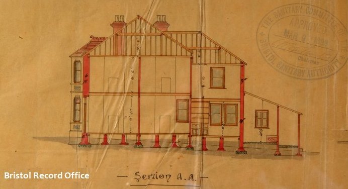
The drawing below shows a section of a proposed house (Bristol 1898). You an see the main walls have brick footings with concrete below.

The London County Council was created in 1889, and sponsored the London Building Act of 1894 which amended the rules relating to foundations and the thickness of external and party walls. This seems like a backward step – they no longer mention concrete footings, instead relying just on brick ones. A writer at the time noted, “the bye-law on the whole is a wise one, as concrete is so easily scamped, but there are many cases in which concrete alone would be more economical and more stable”.

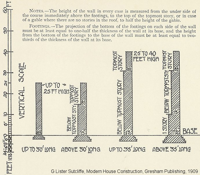
Part of the requirements for external walls and footings from The London Building Act 1984 is shown below. By today’s standards the foundations seem very shallow; in fact many text books from the time suggest that foundations should never be less than 12 inches (300mm) deep and often much more. These standards were generally higher than those adopted by provincial towns and cities.

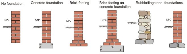
Many local authorities were slow in adopting Model Bye-laws; even where they did, building control was fairly lax. This meant that the nature and quality of foundations varied considerably. The graphics below show typical foundations at the end of the 1800s. The depths varied according to circumstances but generally they were shallower than their modern counterparts.

The drawing below dates from 1903 and shows a section through a planned house. The foundations look quite shallow (and there are no brick footings). Whether or not this was just a drawing convention of the time we do not know; presumably the depth of the actual foundation would depend on specific circumstances.

Reinforced foundations were not unknown. G Lister Sutcliffe states, “..frequently the metal is in the form of steel rails….or twisted wires…  embedded in the concrete.  A stronger foundation can be obtained in less depth than when concrete alone is used”.

Between the Wars

During the 1920s and 30s foundations remained much the same. Text books from the 1930s suggest that in clay soils foundations should be 3 feet deep (900mm) – guidance in fact not much different from today.  London Building Acts and Model Bye-laws introduced a number of minor amendments (see below). The examples below were suitable for houses with foundations in firm clay or coarse sand.

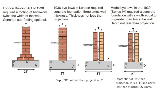
Note that the 1939 bye-laws still permitted brick footings and also mentioned the option of rafts and piles.

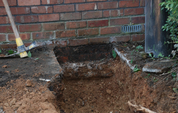
The foundation below was built in the early 1930s.  It’s about 500mm wide, 200mm thick and probably 400mm, or so, deep.

Post 1945

In the late 1940s and throughout the 1950s most new houses were built with strip foundations. Raft foundations were also popular, particularly under system-built properties or over areas of fill. A typical raft comprised a concrete slab 6″ to 9″ thick (150mm to 225mm), suitably reinforced. A few foundations were piled – short bored piling systems became common during the early 1960s. The piles were typically 6′ to 12′ long (1.8 to 3.6m), not normally reinforced but with a reinforced ground beam over the top, cast on some form of compressible material (ash or clinker).

The Model Bylaws were replaced by National Building Regulations in 1965. These Regulations were applied generally throughout England and Wales, with the exception of the Inner London Boroughs (the area of the former London County Council) where the London Building Acts continued to prevail. Various amendments and revisions to these Building Regulations were issued increasing the scope and areas covered by Building Regulations. This continued until the Building Act 1984 finally consolidated Building Regulations under one piece of legislation. This resulted in the introduction of the Building Regulations 1985 that came into operation in November 1985.

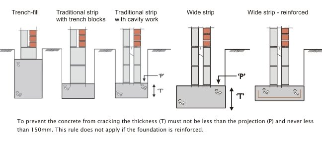
The Building Regulations contain ‘deemed to satisfy’ provisions for strip foundations. For modest loads and on certain types of ground acceptable strip foundation widths are given – see the Building Regulation section for the table itself.  Outside these boundaries, for example a 4 storey building on soft clay, the foundation has to be specifically designed.

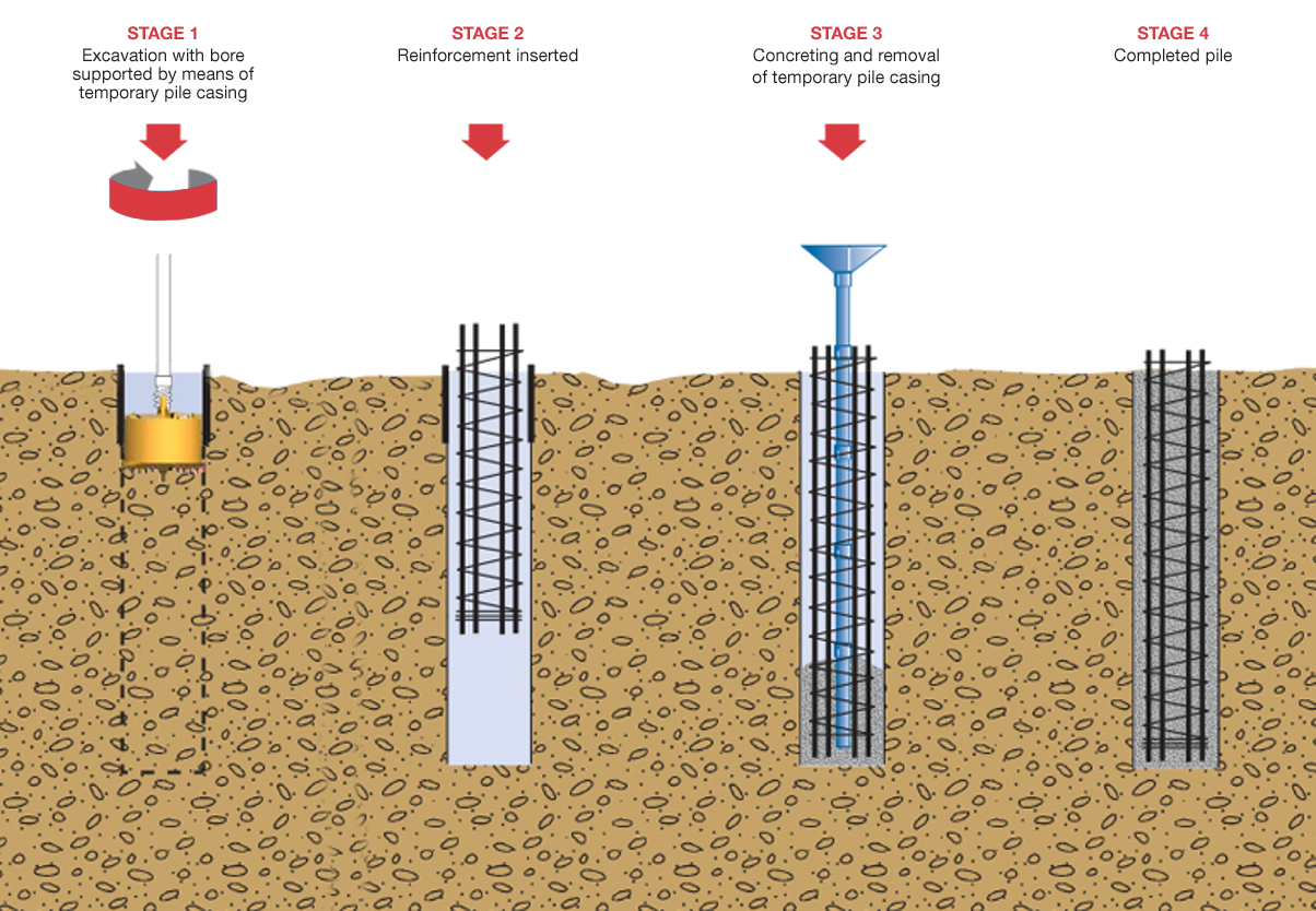
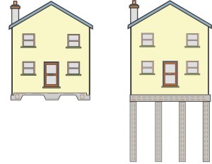
Raft foundations and piled foundations do not have any ‘deemed to satisfy provisions’ and always need to be designed.  Today, rafts are comparatively rare except in former mining areas. Piling has become very common for four main reasons; it’s much cheaper than it used to be, smaller, lighter piling rigs are now available, shoring traditional trenches is expensive, and brownfield sites are often not suitable for strip foundations.

There is much more information on piling in the Foundations section of this web site.

2 External walls

Early Brickwork

During the 1700s there were a number of improvements in brick making. Blended clays, better moulding techniques and more even firing gave greater consistency in brick shape and size. Fashion dictated brick colour: the reds and purples popular in the late 1600s gave way to softer brown colours in the 1730s. By 1800 the production of yellow London stocks provided a brick colour not that much different from natural stone. The repeal of the brick tax in 1850 gave the brick industry a new impetus. Improved mixing and moulding machines, together with better firing techniques, allowed brick production to reach new heights. Bricks were now available in a range of colours, shapes and strengths that would have been unimaginable a 100 years earlier. Better quarrying techniques allowed extraction of the deeper clays which produce very strong, dense bricks; vital for civil engineering works such as canals, viaducts sewers and bridges.

Brick bonding

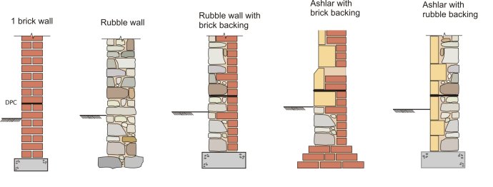
By the end of the 19th century most houses had walls of at least one-brick thickness. Houses over three storeys often had thicker walls, usually reducing in thickness at each upper-floor level. The brickwork itself (at least the brickwork on view) was generally laid to a very high standard. Most houses were built in Flemish bond although rear walls or walls hidden by render were often laid in Garden wall bond (usually English).

Stonework

Stone was often used for prestigious buildings or in areas where it naturally occurred. In upland areas (the north and west) stone was often the obvious choice for building because it was readily available (and prior to the railways these were often areas where bricks were expensive). There are 3 groups of stone; igneous, sedimentary and metamorphic. The sedimentary group, which includes limestone and sandstone, accounts for most of the stone used for building in the UK.

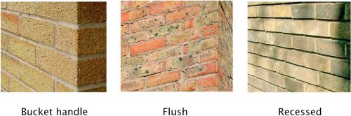
Rubble walling is found in a variety of styles. At its cheapest it comprises rough stonework, built as two outer leaves and bound together with copious amounts of lime mortar. More expensive work comprised squared rubble possibly set against a brick backing. In most situations a stone wall has to be thicker than a brick one. So, whereas a 1 brick thick wall (215mm or so) might be fine for a two or three storey house, a stone wall is likely to be 325mm or even more. Most rubble walls were pointed flush or slightly recessed. The ribbon pointing so often seen nowadays is not traditional, neither is it particularly durable.

Stonework which is dressed and/or finely cut is often referred to as dimensioned stone. Sometimes it’s referred to as freestone. This means it can be worked (cut, shaped and smoothed) with a chisel and a saw in any direction. It has a fine grain and is free from obvious laminations and pronounced bedding planes. In the 18th century whole cities were built (some rebuilt) in stone. It was not cost effective to build the whole of the wall in freestone and a backing material of rubble or brickwork can nearly always be found. In some houses only the front elevation would be built in freestone, the sides and back being constructed of rubble or brick. To bond the two halves of the wall together, ‘through’ or bonding stones were used.

Where the freestone is laid with very fine joints, almost invisible from more than few feet away, the work is knows as ashlar. In some parts of the country the stones were cut with a taper to make the joints easier to form. Wedges made from bits of timber or even oyster shells were often pushed into the back to provide stability as the mortar set. These buildings were built with lime mortar which hardened very slowly. Hydraulic limes were not unknown but they were less common and more expensive. In addition they often set too quickly resulting in high waste on site.

Mortar

Lime mortars were common until the 1930s, in some parts of the UK, even later. Limestone or chalk was burnt with coal to form Quicklime. The burnt lime is known as lump lime. The Quicklime was then slaked with water and then mixed with fine aggregates (nowadays sand) to form mortar. It could take many months for a lime plaster to fully set. Then process is known as carbonation. Some limes have a hydraulic set (a bit like a weak cement). This could be induced by adding pozzolans which contain silica. Another option was to use a lime which naturally contains silicas (usually a proportion of clay). A hydraulic ‘set’ is quicker and stronger than carbonation. Some of the very strong hydraulic limes are not dissimilar to modern cement; made of course, from chalk and clay.

During the 1930s and 1940s cement mortars gradually replaced lime ones. Lime was often added to the mix to improve its working and qualities and durability. More detail can be found lower down the page.

Pointing

In the early 1900s period joints were usually finished flush or slightly recessed.  Where very good quality bricks were used the joints were often only 8mm, or even less. This, together with the use of brick dust in the mortar, meant that the mortar had very little affect on a building’s appearance. Working-class housing was usually pointed in a lime mortar which included local industrial waste products as fine aggregate. Perhaps ash was the most common. The photos below show three examples of good quality 19th century brickwork.

Tuck pointing was usually reserved for the best quality work. Tuck pointing is basically in two parts, a bedding mortar often containing aggregates to match the colour of the bricks or stonework, and a thin ribbon of lime pointing to finish the joint. From a distance a wall that is tuck pointed appears to be finely jointed.  Examples of tuck pointing can be found under the Walls section of this web site.

Cavity walls

In the latter part of the 19th century a number of houses were built with cavity walls. It was not, however, until the 1920s that this became the accepted form of construction. Cavity walls were cheaper to build than their solid wall counterparts. In addition they offer improved thermal insulation and better weather protection. Most walls comprised two half-brick leaves with a 50mm cavity. The two halves of the wall were tied at regular intervals with steel or wrought iron wall ties. The external leaf of brickwork was laid in facing bricks, the internal leaf in commons. A few early cavity walls had an external leaf one brick thick and, in some early forms of construction, the DPC ran right across the cavity.


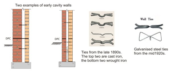
DPCs (to prevent rising damp) were in common use by the early 1900s. They could be made from lead, pitch, asphalt and slate. Not until the mid 1920s did vertical DPCs become a standard detail around openings.

1930s to 1960s

During this period cavity walls changed little. Mortars gradually became cement-based rather than lime-based because the faster setting mortar meant faster construction. Blockwork became a common material for the inner leaf of cavity walls – the blocks were usually made with an aggregate of stone or industrial waste (clinker and breeze were common). A few houses, usually Modernist-style houses with a rendered finish, were built with walls of solid blockwork (i.e. non cavity).

Note that during the 1950s and early 1960s several thousand houses were built in non-traditional construction. These were often constructed using precast frames or panels; in some cases insitu panels. Some systems were based on timber. For more information go to the System Building section of the web site.

1970s to 1980s

In the 1970s insulation standards slowly improved. A maximum ‘U’ value of 1.70 was introduced in 1972 (a measure of a the wall’s ability to transmit heat – explained further in the Walls section). Achieving this standard was relatively easy; a brick external leaf, a 50mm cavity, and a dense block inner leaf finished with 13mm lightweight plaster, just made the 1.7 threshold. In 1980 the maximum U value dropped to 1; this required lightweight blockwork in the inner leaf. From this period to the present day most lightweight blocks have been made from aerated concrete. They were (and still are) made from cement, lime, sand, pulverised fuel ash and aluminium powder.  Once these materials are mixed with hot water the aluminium powder reacts with the lime to form millions of tiny pockets of hydrogen.  However, there are several other materials for blockwork which have enjoyed brief popularity. These include concrete blocks faced with insulation, hollow blocks containing polystyrene granules and blocks made from pumice or no-fines concrete.

Modern cavity walls

In the 1990s the maximum U value dropped to 0.45; this normally required a very thick lightweight inner leaf or cavity insulation. There are three common options, most of which require lightweight or aerated blocks in the inner leaf. These are:

  • a clear cavity with an insulated dry lining
  • insulation boards which partially fill the cavity
  • insulation batts which fill the cavity.

It is still possible to build solid walls – but this is impractical using brick. Only aerated concrete will give acceptable levels of insulation.


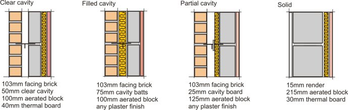
At the time of writing (2006), U values have to less than 0.3 so a modern cavity wall has a ‘U’ value some 5 or 6 times better than its 1920s counterpart. In the above examples slightly thicker insulation will give a U value of 0.30. In modern construction cavity widths have increased well beyond the 50mm common 80 years ago. A 50mm clear gap is required if board insulation is used. This commonly requires a cavity 90mm wide.

Wall Ties

Wall ties are now mostly stainless steel. There are various patterns; the washer shown below is to hold insulation boards in position against the inner leaf. These particular ties are all made by Ancon.

Modern mortars

Modern mortars are made from cement and sand. Hydrated lime (i.e. bagged lime) is often introduced into the mix to give it a more plastic feel and to make it more ‘workable’.  Lime also improves the mortar’s ability to cope with thermal and moisture movement. In recent years the use of pre-mixed mortars has become common. These are delivered to site in sealed containers, ready for use. They usually contain a retarder so they remain usable for 36 – 48 hours or so. At the end of this period they develop their strength in the same way as normal mortars.

The face of the joint may be finished in a number of ways – the three most common are shown below. Tooled joints (where the mortar is pressed against the brickwork) offer the best weather protection because the tooling smoothes and compresses the joint.

This is a copy of an older ‘hand out’ on evolution – you may find it useful.The images are pre-publication proofs from ‘House Inspector’.

3 Ground Floors

Early Timber Floors

Most houses at the end of the Victorian period (1900) were built with suspended ground floors. There were exceptions to this. Many houses had ground floors constructed with stone or clay flags; basements too were covered with flags.  These were laid on a bed of ashes or directly onto compacted earth. Houses without basements usually had a scullery at the back of the house, often in a rear extension. Most sculleries had solid floors – they were used for washing and were likely to stay wet for long periods. The scullery floor was often 6 inches or so (150mm) below the main house floor in case of leaks or flooding. Some of these solid floors were made from concrete.

A typical suspended timber floor from about 1900 comprises a series of joists supported by external and internal loadbearing walls and covered with floorboards.  Deep joists were expensive (they still are) and to reduce joist size there were usually intermediate supports known as sleeper walls. These are small walls in rough stone or brickwork built directly on the ground or on small foundations. In practice, ground-floor joists are often half the depth of those used in upper floors where, of course, such intermediate support is not possible.

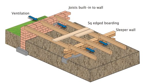
The joists are typically 100mm x 50mm and are usually at 400mm centres or so (16inches). To ventilate the sub-floor void terra cotta or cast iron air bricks were built-in to the external walls. In practice ventilation was not always effective, partly because there were not enough vents and partly because these houses were terraced. This meant that there were only two external walls. In addition, the sleeper walls were not always honeycombed (i.e. with ventilation gaps); this impeded cross ventilation.

Towards end of the Victorian period DPCs, often formed in brittle materials such as slate, were becoming common (but by no means universal). These helped protect the joist ends from rising damp.

In practice such floors often give rise to expensive maintenance problems due to poor design and varying standards of workmanship. They were generally badly ventilated, often prone to flooding (the ground level under the floor was often lower than the ground outside), and the joist ends are always at risk because they are normally only protected by a half-brick thickness of wall.

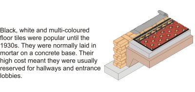
Some houses had concrete floors in the hallways, or maybe just in the lobby by the front door. These were usually covered with decorative tiles laid in mortar on a concrete slab (left).

The 1920s

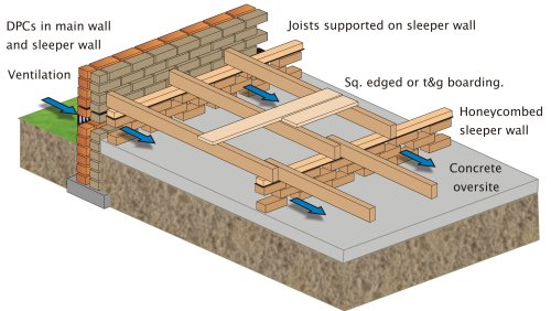
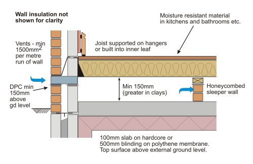
During the first 20 years of the century suspended timber floors changed. A number of improvements were introduced, mostly damp related. In the graphic below note that the entire floor is separated from the substructure by the DPCs. In addition, the bare earth is covered with a concrete slab (often referred to as an ‘oversite’) which is at, or above, external ground level to prevent the build up of water.  The slab also prevents growth of vegetation. The floor joists are supported by honeycombed sleeper walls, through which air can pass easily, and the joists do not touch the external wall. Because most of these houses were detached or semi-detached, rather than terraced, the underfloor void is relatively easy to ventilate.

Ground bearing concrete floors – 1950s

Concrete ground floors were not unknown in the 1930s but they became more common in the 1950s because of the post War restrictions on imported timber (restrictions lasted for nearly 10 years). The floor is basically a bed of concrete, supported by the ground directly beneath it, and quite independent of the surrounding walls.

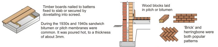
A typical floor from the 1950s might comprise a layer of hardcore (stone or broken brick), a concrete slab probably 100 to 125mm thick and the floor finish. This is often timber to disguise the nature of the floor, or, in cheaper construction, thermoplastic tiles laid in bitumen adhesive. Some floors, by no means all, contained damp proof membranes, usually liquid based.

In many houses the only barrier to rising damp was the bitumen bedding material under the wood blocks or thermoplastic tiles. Thermoplastic tiles were first produced in the UK just after the Second World War. The tiles were made from a mixture of resin binders, mineral fillers, asbestos and pigments. Most were 9 inches square (225mm). Early tiles were quite brittle. Asbestos vinyl tiles were introduced in the mid 1950s; they were made in much the same way but they were more flexible.

Ground bearing concrete floors – 1960s to 1990s

From the mid 1960s to the mid 1990s a typical concrete floor comprised a layer of hardcore, a polythene damp proof membrane laid on a thin bed of sand (to prevent puncturing), and a floor screed.

Hardcores varied in quality – many have since proved to be totally unsuitable. In the mid 1960s polythene damp proof membranes were introduced and became an accepted form of damp proofing.  This barrier was usually laid below the concrete slab. DPMs on top of the slab, i.e. sandwiched under the screed, were also common and usually in liquid form, e.g. hot bitumen, or cold bitumen in solution.  Liquid DPMs gave the best protection but were more expensive. The concrete slab was usually 100 to 125mm thick. In certain situations, i.e. where the ground was uneven or where there were soft spots below the slab, it might be reinforced with a mesh.

The floor screed provided a smooth finish suitable for carpets or tiling. It was laid towards the completion of the building prior to hanging the doors and fixing the skirtings. It was (and is) is a mixture of cement and course sand (typically one part cement to three or four parts sand) mixed with the minimum amount of water and laid to a thickness of 38-50mm. A few floors had a DPM formed in 20mm asphalt. This could be trowelled to a level finish and precluded the need for a separate screed.

Modern Concrete floors

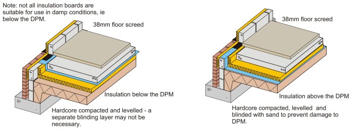
Since the mid 1990s the Building Regulations have required insulation in ground floors.  A variety of manufacturers produce a range of rigid insulation boards which can be laid above or below the slab. Some of the boards have a closed-cell structure and are impervious to both water and vapour.  They can therefore be laid under the DPM (the DPM is still necessary to prevent moisture rising between the board joints and penetrating the slab). Where boards are laid under the DPM blinding is not always necessary. Typical construction is shown below.
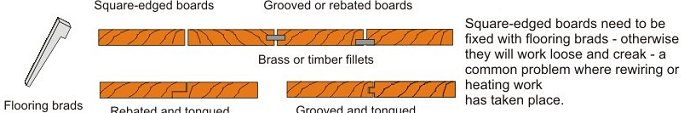
Chipboard flooring

In modern construction chipboard floating floors have become a common alternative to a sand/cement screed. Chipboard and strand board are both very sensitive to moisture and a vapour control layer is normally required under the boarding to prevent drying construction water (i.e. in the concrete) affecting the floor. This membrane is in addition to the DPM below the slab. The tongued & grooved boarding has glued joints and normally sits on a resilient layer of insulation; a perimeter gap of 10mm or so allows for moisture and thermal expansion. This gap is covered by the skirting.

Suspended concrete floors

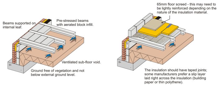
In certain conditions the use of a ground bearing slab is not suitable. In these situations it is common to find a suspended concrete floor.  In fact, nowadays, many developers prefer to use suspended concrete floors in all situations because of the perceived risks of ground bearing floors. Until the 1970s these floors were often constructed from insitu concrete but they were slow to construct and very expensive. Nowadays, the floors are usually made from a series of inverted ‘T’ beams, 150-200mm thick, with a concrete block infill. The two most popular finishes are screed or particle board, both laid on insulation.

Nowadays the Building regulations require that the underfloor space is vented; before 2004 it was only necessary to ventilate the space if the ground was not well drained or if there was a risk of gas build-up. DPMs are not required as long as minimum recommended gaps between floor soffits and sub-soil are maintained.

Modern timber floors

In modern construction timber floors are, once again, becoming popular. The construction is similar to that of 70 years ago although there are a few differences:

  • joists will be supported on hangers rather than built into the walls.
  • timbers are nowadays usually treated against rot and insect attack.
  • rules for ventilation are more onerous than in the past.
  • most floors will be finished with chipboard and floors will be insulated.

This is a copy of an older ‘hand out’ on evolution – you may find it useful. It includes two pages on upper floors. The images are pre-publication proofs from ‘House Inspector’.

4 Upper Floors

Introduction

The upper floor of a modern house is not that much different from its 1800 counterpart. In other words it comprises a series of timber joists (there are modern alternatives) covered with some form of floor boarding. Nowadays we always expect to find a ceiling although, 150 years ago, the joist soffit was often left open in working-class housing. In modern construction the size and spacing of the joists are subject to the Building Regulations. Before 1965 they were mostly controlled by Model Bye-Laws or accepted building practice.

Note that this brief introduction does not include the construction of floors between flats. Information on this can be found under the Floors section of this web site.
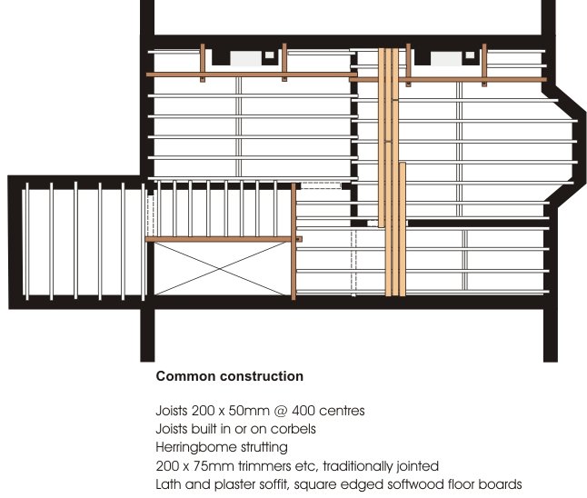
Late 19th century

At the end of the 19th century a typical well-built terraced house would have an upper floor constructed from 8″ by 2″ (200 x 50mm) softwood floor joists fixed at 12″ to 16″ centres (300 to 400)mm. The joists were usually built in to the walls although occasionally wrought iron or brick corbels were used. Corbels were expensive but did ensure that joists on party walls did not penetrate the brickwork (better sound and fire protection) and that joists on external walls were protected by the full thickness of the wall (less chance of rot).

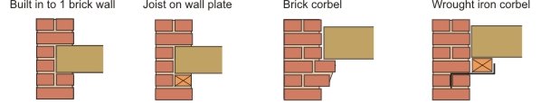
The floor was normally covered with square-edged softwood boards and finished with a lath and plaster ceiling – usually 3 coats of lime plaster. The direction of the joists can either be party wall to party wall, or front to back. The joists were trimmed around fireplaces and stair openings as shown in the graphic.  A half-barrel vault supported the hearth. Note that more information on fireplace construction can be found in the Heating section of this web site.

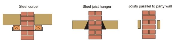
Larger properties may have had double floors, in other words a floor with a primary timber (or steel) beam running at right angles to the joists and supporting them mid span. An advantage of a double floor is that it keeps the floor depth to a minimum and provides all four walls with lateral restraint. Larger, more prestigious, properties sometimes had various types of tongued and grooved boards rather than square edged ones. These are shown further down the page.

1930s

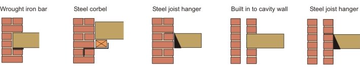
In the 1930s the construction was much the same. Contemporary text books show a number of alternative methods of supporting the joists to suit a Model Bye-law of the time which required that no timber could be built within a half brick of the centre of a party wall. The bye-law also specified that all joists should rest upon a wall plate or steel bearing bar (to spread the load across the wall). In practice these bye-laws were often not adopted by local authorities or just ignored.  Text books also suggested that joist ends should be tarred or creosoted where they were built into walls.

‘Specification’ from 1931 provides some general guidance on the construction of upper floors (interestingly enough it does not mention the bye-law requirements). Single floors were normally thought to be acceptable for floor spans up to 16 feet; above that double floors were recommended.

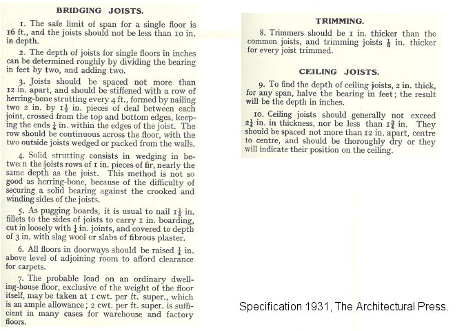
Herringbone strutting was normally recommend at 6 feet intervals (1.8 metres). Unlike Victorian and Edwardian floors the hearth support was often in the form of insitu concrete reinforced with mesh rather than a half barrel vault.

1950s and 1960s

In the post War period timber imports were strictly controlled. Although some system-built houses had floors made from steel joists  most houses had fairly traditional upper floors, often with centres ‘stretched’ and joist sizes reduced, to save timber. In addition strutting was often omitted. Floor coverings were usually tongued and grooved softwood. Boarded ceilings replaced lath and plaster – fibre board, asbestos board and plasterboard (often small sheets – i.e. plasterboard lath) were all common. Joists were built-in or supported on hangers.

By the 1960s timber rationing was over and floor timbers reverted to pre-War sizes. The 1965 Building Regulations introduced tables for sizing floor joists and these remain much the same to this day. During the 1960s plasterboard became virtually the only material used for ceilings. The boarding was normally 10mm or 12.5mm thick (3/8inch or 1/2inch) with an artex or gypsum plaster finish.

Modern floors

The construction of modern upper floors is shown below. They differ from 1950s floors in three main ways: strapping is now required to restrain the external walls, joist hangers are almost obligatory (to prevent air leakage), and floor boards have largely been replaced by chipboard or strand board. Modern ceilings are still nearly always formed in plasterboard.  Nowadays plasterboard lath is rare; the construction usually consists of large sheets of 15mm plasterboard, screwed to joists or to resilient bars, and then taped and painted.

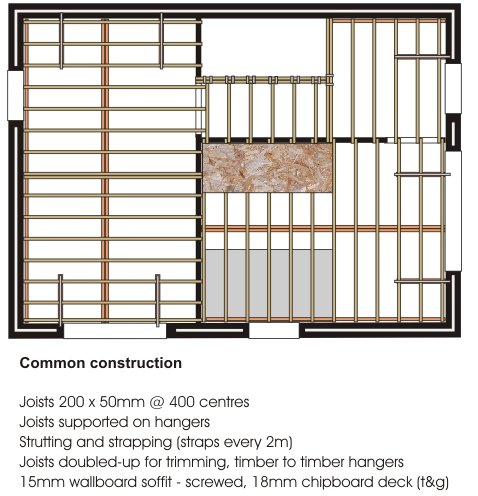
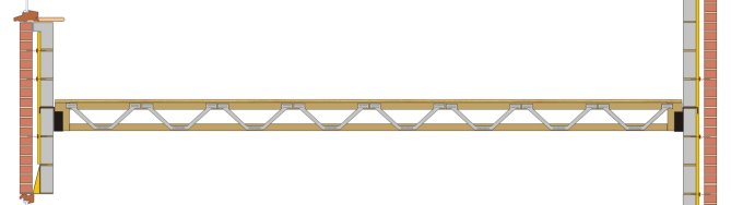
In recent years the use of metal web joists and ‘I’ joists has become more common. In principle these are no different from traditional ‘cut’ joists. One advantage is that they are capable of increased spans. The use of metal web joists also precludes the need for potentially damaging joist notching.

Flats

In flats the floors separate dwellings and, therefore, must provide good fire protection and resistance to the passage of impact and airborne sound. The methods of construction shown above are not suitable. Modern options and a brief historical overview can be found in the Floors section of this web site.

5 Roof Structure

Introduction

During the 19th century the construction of domestic roofs changed little. In the late 1800s timbers were cut by machine rather than by hand, and fixings in the forms of nails, screws and bolts were cheaper and more readily available, but the nature of the structure was much the same as it had been 100 years earlier.

1900s

A typical roof comprised a series of sloping timbers known as rafters fixed, at the top to a ridge board, and at the bottom to a wall plate. Ceiling joists supported the ceiling and acted as a tie to the rafters – to stop the rafter feet from spreading. A binder running at right angles to the ceiling joists could be added to help prevent deflection in the joists. In some houses the binder was connected to the ridge by a hanger, again to prevent deflection.

This type of construction could be adapted for larger roofs. The roof shown on the right is the same in principle although there is an additional timber known as a purlin which prevents the rafters from sagging mid span.   The purlin is supported by the gable-end walls (party walls in mid-terraced houses) and is sometimes strutted from an internal loadbearing wall (and sometimes the gable walls) to a provide additional support.

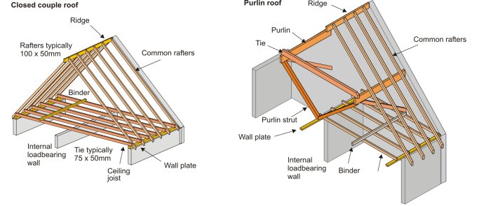
The feet of the rafters were designed to provide a roof overhang or to finish flush with the wall. A fascia board at the feet of the rafters finished off the roof and supported the cast iron or, in a few cases, timber guttering.

Some very large houses with big rooms did not have an internal loadbearing wall in an appropriate position. Other ways had to be found of supporting the purlins mid span. King and Queen post trusses could be used in this instance. These were also widely used in factories and warehouses where large uninterrupted spaces were required.

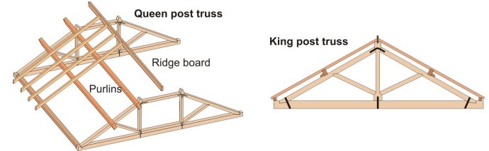
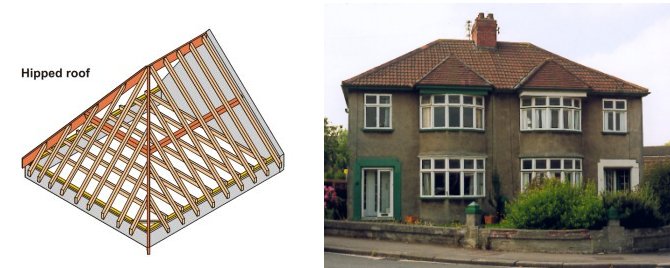
Nearly all the roofs built before 1940 would have been based on the closed couple or purlin design. Sometimes the style was adapted slightly. A hipped roof (below) is a different shape but the arrangement of the timbers is much the same. Larger examples had strutted purlins; larger examples still, had trusses – usually one full truss spanning front to back, and a half truss supporting the end (hip) purlin.

Post War Years

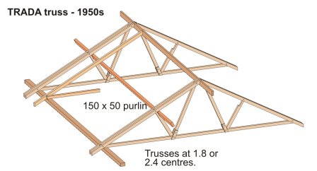
During the War 500,000 homes were damaged or destroyed. In the post War period there was a massive building programme not just to rebuild these damaged homes but also to continue the slum clearance work of the 1930s. But, at the same time, there was a chronic (it lasted for nearly 10 years) shortage of materials. In an attempt to avoid economic disaster the government placed strict limits on the import of materials. Timber was in short supply and new techniques had to be found. At ground floor level timber was saved by building floors in concrete. This was not a practical solution for roofs (apart from a few flat roofs in system-built houses) so techniques were developed which would reduce the amount of timber used in a roof. The TRADA truss is basically a lightweight version of the trusses shown above. They did away with the need for internal loadbearing walls upstairs and allowed for smaller section rafters – often at slightly wider centres. They were common during the 1950s.

Trussed rafters

The TRADA truss was relatively short lived.Most modern roofs are constructed from trussed rafters; they have been popular since the 1960s. The most common pattern is the Fink or ‘W’ truss designed for symmetrical double-pitch roofs although there are a variety of shapes suitable for most roof designs.  The trussed rafters are prefabricated and delivered to site ready for lifting onto the supporting walls, although occasionally you will find the entire roof structure assembled on the ground and lifted into place by crane.

The timbers, which are typically 80 x 40mm in section, are butt-jointed and held together by special plates (first introduced to the UK in the mid 1960s) which are pressed into position by machine.  Nowadays the timber are normally pre-treated to guard against rot and insect attack.


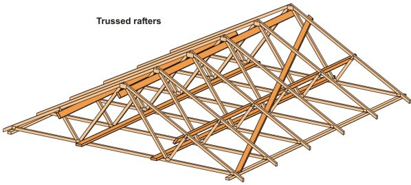
Trussed rafters offer several advantages when compared to traditional roofing methods.

  • No internal support is required from loadbearing partitions.
  • Spans of up to about 12 metres can easily be achieved.
  • They offer vary fast construction.
  • Skilled labour is not required.
  • They are relatively cheap.
  • They can be designed with very shallow pitches.

Perhaps their major disadvantage is that use of the roof space for storage (when using normal trusses) is severely limited due to the nature of the timbers. When the trusses are in position additional timbers (braces) need to be added to produce a strong, rigid roof structure. These are explained elsewhere on this web site.

New ‘cut’ or traditional roofs are sometimes still found but they tend to be one-off dwellings often with living accommodation in the roof space.

Modern trussed rafters and traditional roofs are both supported on softwood wall plates bedded in mortar on the inner leaf of the cavity wall. It’s normal practice to strap the roofs to the blockwork inner leaf to prevent them lifting or moving in high winds. Modern roofs are normally ventilated to help minimise condensation. This is usually done by installing air vents at the eaves. There are other methods and these are explained elsewhere on this web site.

This is a copy of an older ‘hand out’ on evolution – you may find it useful. The images are pre-publication proofs from ‘House Inspector’.

6 Windows

Early windows were usually fixed lights or side-hung casements. All the examples below are mid to late 17th century. The timber window on the far left is part of a timber framed house built in Bristol’s dock area. The second example shows a stone building (c1690) with timber window frames glazed with diamond shaped leaded glass (small panes of glass were much cheaper than large sheets). A hinged, wrought iron casement has been fitted into the right hand section of window. The window on the right has a fixed light directly glazed into the stonework and a hinged iron casement.

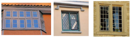
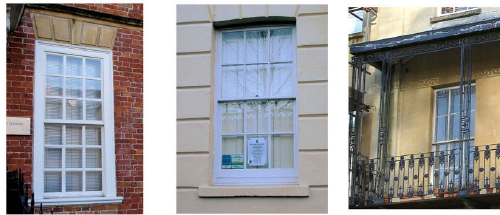
In the late 17th century sash windows were introduced to Britain. These windows were usually still formed in small panes because of the limitations of glass technology. The timber sections were quite thick and the window was set flush with the face of the brick or stonework (left hand photo – about 1710). The windows were controlled with lead (later iron) weights which counter-balanced the weight of the sashes. During the Georgian period the glazing bars became thinner and thinner and, at the same time, the windows were set in rebates which hid the box frames. In houses with thick walls the inner reveals often contained shutters (centre photo – about 1800). From the late 18th century onwards it became fashionable (for the wealthy at least) to have full length windows on the first floor leading onto a wrought and cast iron balcony.

Windows are visually important architectural elements. For example windows were integral to the architectural philosophy of the Georgian era, where their proportions were closely defined in relation to the dictates of symmetry. During the Georgian era window tax was introduced. This was levied on the number of windows in a house and goes some way towards explaining why some windows from this era were blocked up. In the middle of the 19th century this tax was dropped. This change was accompanied by increasing concern with daylight and ventilation, which the Victorians associated with good health. Consequently there was a move towards stipulating minimum window sizes. Towards the end of the Victorian period improvements in glass technology precluded the need for glazing bars altogether.

In the 1920s top hung and side hung casements became popular. The example on the left is from about 1920 and is a crude example of Queen Anne revival sash windows; they were popular during the Edwardian period and were characterised by having a small-paned top sash over a single paned bottom sash – white paint was de rigeur. The right-hand example is from the mid 1930s; casement windows with top hung leaded top-lights (often glazed with stained glass).

Metal windows, introduced in the very late 19th century, were very common until the 1970s. Early windows were plain mild steel; from the 1930s they were mostly galvanised. As houses became better insulated and less well ventilated their shortcomings became more obvious – the cold inner face of the frames resulted in condensation.

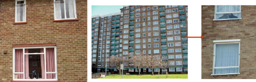
In the post war period high rise housing required new approaches to window styles. Traditional sash windows could not possibly withstand the turbulence and exposure at high levels, and casement windows would be impossible to clean. A common form of window was the horizontal pivot window. These could be made from galvanised metal, timber or aluminium and could be cleaned from the inside.

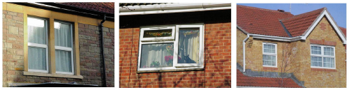
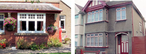
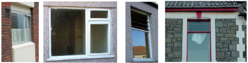
Aluminium windows (below left) became very popular during the 1970s but, in recent years, have almost completely been eclipsed by plastic. Aluminium windows, like galvanised metal, are good conductors of heat and condensation is always likely to be a problem. In the 1970s a policy of rehabilitating older properties replaced slum clearance and high rise construction. In many cases budgets were not adequate and houses, originally refurbished for 30 years or so, required substantial extra investment after less than 10 years. One example of cost cutting was the louvre window (below right). These were cheap to make, just requiring a simple softwood frame, but were draughty, provided inadequate ventilation in the Summer, and could not readily be used as a means of escape. Other rehab and new houses were fitted with ‘standard’ timber windows. There were hundreds of styles (below middle). These windows were cheap but mostly made from poor quality timber.

Nowadays, windows are usually made from imported softwoods and hardwoods, or from plastic. There are literally hundreds of styles to choose from. The public has become accustomed to renewing windows, almost as fashion accessories, and often well in advance of their likely life. Because of this, replacement windows has become a very big, but in some cases completely unnecessary, business. The design of windows and the choice of material used may be controlled by planning authorities in conservation areas. Plastic replacement windows are a focus for concern in such areas because they affect character and appearance. Even outside conservation areas the replacement of wooden sash windows will have a significant visual affect on say a street of Victorian terraced houses (below right). The windows on the far right are mock Georgian; the glazing bars are sandwiched between the double glazing.

Bearing Capacity Technical Guidance

http://www.geotechnicalinfo.com/bearing_capacity_technical_guidance.html

Bearing capacity of soil is the value of the average contact pressure between the foundation and the soil which will produce shear failure in the soil. Ultimate bearing capacity is the theoretical maximum pressure which can be supported without failure. Allowable bearing capacity is what is used in geotechnical design, and is the ultimate bearing capacity divided by a factor of safety.

Theoretical (Ultimate) and allowable bearing capacity can be assessed for the following:

  • Shallow Foundations
    • strip footings
    • square footings
    • circular footings
  • Deep foundations
    • end bearing
    • skin friction

For comprehensive examples of bearing capacity problems see:

  • Bearing Capacity Examples

Allowable Bearing Capacity


Qa   =    Qu                                 Qa = Allowable bearing capacity  (kN/m2) or (lb/ft2)
     F.S.

Where:

Qu = ultimate bearing capacity (kN/m2) or (lb/ft2)                *See below for theory
F.S. = Factor of Safety

Ultimate Bearing Capacity for Shallow Foundations


Terzaghi Ultimate Bearing Capacity Theory


Qu = c Nc + g D Nq + 0.5 g B Ng
= Ultimate bearing capacity equation for shallow strip footings, (kN/m2) (lb/ft2)

Qu = 1.3 c Nc + g D Nq + 0.4 g B Ng
= Ultimate bearing capacity equation for shallow square footings, (kN/m2) (lb/ft2)

Qu = 1.3 c Nc + g D Nq + 0.3 g B Ng
= Ultimate bearing capacity equation for shallow circular footings, (kN/m2) (lb/ft2)

Where:

c = Cohesion of soil (kN/m2) (lb/ft2),
g = effective unit weight of soil (kN/m3) (lb/ft3),  *see note below
D = depth of footing (m) (ft),
B = width of footing (m) (ft),
Nc=cotf(Nq – 1),                                             *see typical bearing capacity factors
Nq=e2(3p/4-f/2)tanf / [2 cos2(45+f/2)],         *see typical bearing capacity factors
N g=(1/2) tanf(kp /cos2 f – 1),                         *see typical bearing capacity factors
e = Napier’s constant = 2.718…,
kp = passive pressure coefficient, and
f = angle of internal friction (degrees).

Notes:
Effective unit weight, g, is the unit weight of the soil for soils above the water table and capillary rise. For saturated soils, the effective unit weight is the unit weight of water, gw, 9.81 kN/m3 (62.4 lb/ft3), subtracted from the saturated unit weight of soil. Find more information in the foundations section.

Meyerhof Bearing Capacity Theory Based on Standard Penetration Test Values

Qu = 31.417(NB + ND)      (kN/m2)                        (metric)

Qu =   NB    +   ND            (tons/ft2)                       (standard)
10           10

For footing widths of 1.2 meters (4 feet) or less

Qa =   11,970N               (kN/m2)                        (metric)

Qa =   1.25N                   (tons/ft2)                       (standard)
10

For footing widths of 3 meters (10 feet) or more

Qa =   9,576N                 (kN/m2)                        (metric)

Qa =   N                          (tons/ft2)                       (standard)
10
Where:

N = N value derived from Standard Penetration Test (SPT)
D = depth of footing (m) (ft), and
B = width of footing (m) (ft).

Note:  All Meyerhof equations are for foundations bearing on clean sands. The first equation is for ultimate bearing capacity, while the second two are factored within the equation in order to provide an allowable bearing capacity. Linear interpolation can be performed for footing widths between 1.2 meters (4 feet) and 3 meters (10 feet). Meyerhof equations are based on limiting total settlement to 25 cm (1 inch), and differential settlement to 19 cm (3/4 inch).


Ultimate Bearing Capacity for Deep Foundations (Pile)


Qult = Qp + Qf

Where:

Qult = Ultimate bearing capacity of pile, kN (lb)
Qp = Theoretical bearing capacity for tip of foundation, or end bearing, kN (lb)
Qf = Theoretical bearing capacity due to shaft friction, or adhesion between foundation shaft and soil, kN (lb)


End Bearing (Tip) Capacity of Pile Foundation

Qp = Apqp

Where:

Qp = Theoretical bearing capacity for tip of foundation, or end bearing, kN (lb)
Ap = Effective area of the tip of the pile, m2 (ft2)
For a circular closed end pile or circular plugged pile; Ap = p(B/2)2 m2 (ft2)
qp = gDNq
= Theoretical unit tip-bearing capacity for cohesionless and silt soils, kN/m2 (lb/ft2)
qp = 9c
= Theoretical unit tip-bearing capacity for cohesive soils, kN/m2 (lb/ft2)
g = effective unit weight of soil, kN/m3 (lb/ft3),                                *See notes below
D = Effective depth of pile, m (ft), where D < Dc,
Nq = Bearing capacity factor for piles,
c = cohesion of soil, kN/m2 (lb/ft2),
B = diameter of pile, m (ft), and
Dc = critical depth for piles in loose silts or sands m (ft).
Dc = 10B, for loose silts and sands
         Dc = 15B, for medium dense silts and sands
         Dc = 20B, for dense silts and sands


Skin (Shaft) Friction Capacity of Pile Foundation

Qf = Afqf       for one homogeneous layer of soil

Qf = pSqfL    for multi-layers of soil

Where:

Qf = Theoretical bearing capacity due to shaft friction, or adhesion between foundation shaft and soil, kN (lb)
Af = pL; Effective surface area of the pile shaft, m2 (ft2)
qf = ks tan d = Theoretical unit friction capacity for cohesionless soils, kN/m2 (lb/ft2)
qf = cA + ks tan d = Theoretical unit friction capacity for silts, kN/m2 (lb/ft2)
qf = aSu = Theoretical unit friction capacity for cohesive soils, kN/m2 (lb/ft2)
p = perimeter of pile cross-section, m (ft)
for a circular pile; p = 2p(B/2)
for a square pile; p = 4B
L = Effective length of pile, m (ft)                                              *See Notes below
a = 1 – 0.1(Suc)2 = adhesion factor, kN/m2 (ksf), where Suc < 48 kN/m2 (1 ksf)
a =    1    [0.9 + 0.3(Suc – 1)] kN/m2, (ksf) where Suc > 48 kN/m2, (1 ksf)
Suc
Suc = 2c = Unconfined compressive strength , kN/m2 (lb/ft2)
cA = adhesion
= c for rough concrete, rusty steel, corrugated metal
0.8c < cA < c for smooth concrete
0.5c < cA < 0.9c for clean steel
c = cohesion of soil, kN/m2 (lb/ft2)
d = external friction angle of soil and wall contact (deg)
f = angle of internal friction (deg)
s = gD = effective overburden pressure, kN/m2, (lb/ft2)
k = lateral earth pressure coefficient for piles
g = effective unit weight of soil, kN/m3 (lb/ft3)                    *See notes below
B = diameter or width of pile, m (ft)
D = Effective depth of pile, m (ft), where D < Dc
Dc = critical depth for piles in loose silts or sands m (ft).
Dc = 10B, for loose silts and sands
         Dc = 15B, for medium dense silts and sands
         Dc = 20B, for dense silts and sands
S = summation of differing soil layers (i.e. a1 + a2 + …. + an)
Notes: Determining effective length requires engineering judgment. The effective length can be the pile depth minus any disturbed surface soils, soft/ loose soils, or seasonal variation. The effective length may also be the length of a pile segment within a single soil layer of a multi layered soil. Effective unit weight, g, is the unit weight of the soil for soils above the water table and capillary rise. For saturated soils, the effective unit weight is the unit weight of water, gw, 9.81 kN/m3 (62.4 lb/ft3), subtracted from the saturated unit weight of soil.

************

Meyerhof Method for Determining  qp and qf in Sand

Theoretical unit tip-bearing capacity for driven piles in sand, when  D  > 10:
B
     qp = 4Nc  tons/ft2                      standard

Theoretical unit tip-bearing capacity for drilled piles in sand:

     qp = 1.2Nc  tons/ft2                   standard

Theoretical unit friction-bearing capacity for driven piles in sand:

     qf =  N   tons/ft2                         standard
             50

Theoretical unit friction-bearing capacity for drilled piles in sand:

     qf =  N   tons/ft2                         standard
            100

Where:

D = pile embedment depth, ft
B = pile diameter, ft
Nc = Cn(N)
Cn = 0.77 log  20  
s

N = N-Value from SPT test
s = gD = effective overburden stress at pile embedment depth,  tons/ft2
= (g – gw)D = effective stress if below water table,  tons/ft2
g = effective unit weight of soil,  tons/ft3
gw = 0.0312 tons/ft3 = unit weight of water

Examples for determining allowable bearing capacity


Example #1: Determine allowable bearing capacity and width for a shallow strip footing on cohesionless silty sand and gravel soil. Loose soils were encountered in the upper 0.6 m (2 feet) of building subgrade. Footing must withstand a 144 kN/m2 (3000 lb/ft2) building pressure.

Given

  • bearing pressure from building = 144 kN/m2 (3000 lbs/ft2)
  • unit weight of soil, g = 21 kN/m3 (132 lbs/ft3)  *from soil testing, see typical g values
  • Cohesion, c = 0                                               *from soil testing, see typical c values
  • angle of Internal Friction, f = 32 degrees         *from soil testing, see typical f values
  • footing depth, D = 0.6 m (2 ft)                         *because loose soils in upper soil strata


Solution

Try a minimal footing width, B = 0.3 m (B = 1 foot).

Use a factor of safety, F.S = 3. Three is typical for this type of application. See factor of safety for more information.

Determine bearing capacity factors Ng, Nc and Nq. See typical bearing capacity factors relating to the soils’ angle of internal friction.

  • Ng = 22
  • Nc = 35.5
  • Nq = 23.2

Solve for ultimate bearing capacity,

Qu = c Nc + g D Nq + 0.5 g B Ng                                *strip footing eq.

Qu = 0(35.5) + 21 kN/m3(0.6m)(23.2) + 0.5(21 kN/m3)(0.3 m)(22)                 metric
Qu = 362 kN/m2

Qu = 0(35.5) + 132lbs/ft3(2ft)(23.2) + 0.5(132lbs/ft3)(1ft)(22)                          standard
Qu = 7577 lbs/ft2

Solve for allowable bearing capacity,

Qa =   Qu    
F.S.

Qa =  362 kN/m2  = 121 kN/m2                                          not o.k.                 metric
3  
Qa =  7577lbs/ft2  = 2526 lbs/ft2                                          not o.k.                 standard 
3           

Since Qa < required 144 kN/m2 (3000 lbs/ft2) bearing pressure, increase footing width, B or foundation depth, D to increase bearing capacity.

Try footing width, B = 0.61 m (B = 2 ft).

Qu = 0 + 21 kN/m3(0.61 m)(23.2) + 0.5(21 kN/m3)(0.61 m)(22)                      metric
Qu = 438 kN/m2

Qu = 0 + 132 lbs/ft3(2 ft)(23.2) + 0.5(132 lbs/ft3)(2 ft)(22)                                standard
Qu = 9029 lbs/ft2


Qa =   438 kN/m2   = 146 kN/m2          Qa > 144 kN/m2            o.k.                   metric
3

Qa =   9029 lbs/ft2 = 3010 lbs/ft2           Qa > 3000 lbs/ft2           o.k.                  standard
3

Conclusion

Footing shall be 0.61 meters (2 feet) wide at a depth of 0.61 meters (2 feet) below ground surface.Many engineers neglect the depth factor (i.e. D Nq = 0) for shallow foundations. This inherently increases the factor of safety. Some site conditions that may negatively effect the depth factor are foundations established at depths equal to or less than 0.3 meters (1 feet) below the ground surface, placement of foundations on fill, and disturbed/ fill soils located above or to the sides of foundations.

********************************


Example #2: Determine allowable bearing capacity of a shallow, 0.3 meter (12-inch) square isolated footing bearing on saturated cohesive soil. The frost penetration depth is 0.61 meter (2 feet). Structural parameters require the foundation to withstand 4.4 kN (1000 lbs) of force on a 0.3 meter (12-inch) square column.

Given

  • bearing pressure from building column = 4.4 kN/ (0.3 m x 0.3 m) = 48.9 kN/m2
  • bearing pressure from building column = 1000 lbs/ (1 ft x 1 ft) = 1000 lbs/ft2
  • unit weight of saturated soil, gsat= 20.3 kN/m3 (129 lbs/ft3)            *see typical g values
  • unit weight of water, gw= 9.81 kN/m3 (62.4 lbs/ft3)                        *constant
  • Cohesion, c = 21.1 kN/m2 (440 lbs/ft2)                *from soil testing, see typical c values
  • angle of Internal Friction, f = 0 degrees                *from soil testing, see typical f values
  • footing width, B = 0.3 m (1 ft)


Solution

Try a footing depth, D = 0.61 meters (2 feet), because foundation should be below frost depth.

Use a factor of safety, F.S = 3. See factor of safety for more information.

Determine bearing capacity factors Ng, Nc and Nq. See typical bearing capacity factors relating to the soils’ angle of internal friction.

  • Ng = 0
  • Nc = 5.7
  • Nq = 1

Solve for ultimate bearing capacity,

Qu = 1.3c Nc + g D Nq + 0.4 g B Ng                                  *square footing eq.

Qu =1.3(21.1kN/m2)5.7+(20.3kN/m3-9.81kN/m3)(0.61m)1+0.4(20.3kN/m3-9.81kN/m3)(0.3m)0
Qu = 163 kN/m2                                                                                       metric

Qu = 1.3(440lbs/ft2)(5.7) + (129lbs/ft3 – 62.4lbs/ft3)(2ft)(1) + 0.4(129lbs/ft3 – 62.4lbs/ft3)(1ft)(0)
Qu = 3394 lbs/ft2                                                                                      standard

Solve for allowable bearing capacity,

Qa =   Qu    
F.S.

Qa =   163 kN/m2   = 54 kN/m2             Qa > 48.9 kN/m2         o.k.          metric
3
Qa =    3394lbs/ft2   = 1130 lbs/ft2         Qa > 1000 lbs/ft2         o.k.          standard
3

Conclusion

The 0.3 meter (12-inch) isolated square footing shall be 0.61 meters (2 feet) below the ground surface. Other considerations may be required for foundations bearing on moisture sensitive clays, especially for lightly loaded structures such as in this example. Sensitive clays could expand and contract, which could cause structural damage. Clay used as bearing soils may require mitigation such as heavier loads, subgrade removal and replacement below the foundation, or moisture control within the subgrade.

********************************


Example #3: Determine allowable bearing capacity and width for a foundation using the Meyerhof Method. Soils consist of poorly graded sand. Footing must withstand a 144 kN/m2(1.5 tons/ft2) building pressure.

Given

  • bearing pressure from building = 144 kN/m2 (1.5 tons/ft2)
  • N Value, N = 10 at 0.3 m (1 ft) depth                          *from SPT soil testing
  • N Value, N = 36 at 0.61 m (2 ft) depth                        *from SPT soil testing
  • N Value, N = 50 at 1.5 m (5 ft) depth                          *from SPT soil testing

Solution

Try a minimal footing width, B = 0.3 m (B = 1 foot) at a depth, D = 0.61 meter (2 feet). Footings for single family residences are typically 0.3m (1 ft) to 0.61m (2ft) wide. This depth was selected because soil density greatly increases (i.e. higher N-value) at a depth of 0.61 m (2 ft).

Use a factor of safety, F.S = 3. Three is typical for this type of application. See factor of safety for more information.

Solve for ultimate bearing capacity

Qu = 31.417(NB + ND)      (kN/m2)                          (metric)

Qu =   NB    +   ND            (tons/ft2)                         (standard)
10           10

Qu = 31.417(36(0.3m) + 36(0.61m)) = 1029 kN/m2    (metric)

Qu =   36(1 ft)   +   36(2 ft)   = 10.8 tons/ft2                 (standard)
10                10

Solve for allowable bearing capacity,

Qa =   Qu    
F.S
.

Qa =  1029 kN/m2  = 343 kN/m2    Qa > 144 kN/m2      o.k.    (metric)
3  
Qa =  10.8 tons/ft2  = 3.6 tons/ft2     Qa > 1.5 tons/ft2      o.k.    (standard) 
3           

Conclusion

Footing shall be 0.3 meters (1 feet) wide at a depth of 0.61 meters (2 feet) below the ground surface. A footing width of only 0.3 m (1 ft) is most likely insufficient for the structural engineer when designing the footing with the building pressure in this problem.

********************************


Example #4: Determine allowable bearing capacity and diameter of a single driven pile. Pile must withstand a 66.7 kN (15 kips) vertical load.

Given

  • vertical column load = 66.7 kN (15 kips or 15,000 lb)
  • homogeneous soils in upper 15.2 m (50 ft); silty soil
    • unit weight, g = 19.6 kN/m3 (125 lbs/ft3) *from soil testing, see typical g values
    • cohesion, c = 47.9 kN/m2 (1000 lb/ft2)   *from soil testing, see typical c values
    • angle of internal friction, f = 30 degrees   *from soil testing, see typical f values
  • Pile Information
    • driven
    • steel
    • plugged end


Solution

Try a pile depth, D = 1.5 meters (5 feet)
Try pile diameter, B = 0.61 m (2 ft)

Use a factor of safety, F.S = 3. Smaller factors of safety are sometimes used if piles are load tested, or the engineer has sufficient experience with the regional soils.

Determine ultimate end bearing of pile,

Qp = Apqp
Ap = p(B/2)2 = p(0.61m/2)2 = 0.292 m2                                      metric
Ap = p(B/2)2 = p(2ft/2)2 = 3.14 ft2                                                        standard

qp = gDNq

g = 19.6 kN/m3 (125 lbs/ft3); given soil unit weight
f = 30 degrees; given soil angle of internal friction
B = 0.61 m (2 ft); trial pile width
D = 1.5 m (5 ft); trial depth, may need to increase or decrease depending on capacity
check to see if D < Dc
       Dc = 15B = 9.2 m (30 ft); critical depth for medium dense silts.
If D > Dc, then use Dc
Nq = 25; Meyerhof bearing capacity factor for driven piles, based on f

qp = 19.6 kN/m3(1.5 m)25 = 735 kN/m2                                    metric
qp = 125 lb/ft3(5 ft)25 = 15,625 lb/ft2                                          standard
Qp = Apqp = (0.292 m2)(735 kN/m2) = 214.6 kN                     metric
Qp = Apqp = (3.14 ft2)(15,625 lb/ft2) = 49,063 lb                      standard


Determine ultimate friction capacity of pile,

Qf = Afqf

Af = pL

p = 2p(0.61m/2) = 1.92 m                                                            metric
p = 2p(2 ft/2) = 6.28 ft                                                                 standard
L = D = 1.5 m (5 ft); length and depth used interchangeably. check Dc as above

Af = 1.92 m(1.5 m) = 2.88 m2                                                      metric   
Af = 6.28 ft(5 ft) = 31.4 ft2                                                           standard

qf = cA + ks tan d = cA + kgD tan d

k = 0.5; lateral earth pressure coefficient for piles, value chosen from Broms low density steel
g = 19.6 kN/m3 (125 lb/ft3); given effective soil unit weight. If water table, then g – gw
D = L = 1.5 m (5 ft); pile length. Check to see if D < Dc
Dc = 15B = 9.2 m (30 ft); critical depth for medium dense silts. If D > Dc, then use Dc
d = 20 deg; external friction angle, equation chosen from Broms steel piles
B = 0.61 m (2 ft); selected pile diameter
cA = 0.5c; for clean steel. See adhesion in pile theories above.
= 24 kN/m2 (500 lb/ft2)

qf = 24 kN/m2 + 0.5(19.6 kN/m3)(1.5m)tan 20 = 29.4 kN/m2      metric
qf = 500 lb/ft2 + 0.5(125 lb/ft3)(5ft)tan 20 = 614 lb/ft2                  standard

Qf = Afqf = 2.88 m2(29.4 kN/m2) = 84.7 kN                               metric
Qf = Afqf = 31.4 ft2(614 lb/ft2) = 19,280 lb                                  standard


Determine ultimate pile capacity,

Qult = Qp + Qf

Qult = 214.6 kN + 84.7 kN = 299.3 kN                                       metric
Qult = 49,063 lb + 19,280 lb = 68,343 lb                                      standard


Solve for allowable bearing capacity,

Qa =  Qult     
F.S.

Qa   299.3 kN    = 99.8 kN;  Qa > applied load (66.7 kN)     o.k.     metric
3
Qa   68,343 lbs    = 22,781 lbs  Qa > applied load (15 kips)   o.k.     standard
3


Conclusion

A 0.61 m (2 ft) steel pile shall be plugged and driven 1.5 m (5 feet) below the ground surface. Many engineers neglect the skin friction within the upper 1 to 5 feet of subgrade due to seasonal variations or soil disturbance. Seasonal variations may include freeze/ thaw or effects from water. The end bearing alone (neglect skin friction) is sufficient for this case. Typical methods for increasing the pile capacity are increasing the pile diameter or increasing the embedment depth of the pile.

********************************


Example #5: Determine allowable bearing capacity and diameter of a single driven pile. Pile must withstand a 66.7 kN (15 kips) vertical load.

Given

  • vertical column load = 66.7 kN (15 kips or 15,000 lb)
  • upper 1.5 m (5 ft) of soil is a medium dense gravelly sand
    • unit weight, g = 19.6 kN/m3 (125 lbs/ft3) *from soil testing, see typical g values
    • cohesion, c = 0                                        *from soil testing, see typical c values
    • angle of internal friction, f = 30 degrees   *from soil testing, see typical f values
  • soils below 1.5 m (5 ft) of soil is a stiff silty clay
    • unit weight, g = 18.9 kN/m3 (120 lbs/ft3)
    • cohesion, c = 47.9 kN/m2 (1000 lb/ft2)
    • angle of internal friction, f = 0 degrees
  • Pile Information
    • driven
    • wood
    • closed end


Solution

Try a pile depth, D = 2.4 meters (8 feet)
Try pile diameter, B = 0.61 m (2 ft)

Use a factor of safety, F.S = 3. Smaller factors of safety are sometimes used if piles are load tested, or the engineer has sufficient experience with the regional soils.

Determine ultimate end bearing of pile,

Qp = Apqp
Ap = p(B/2)2 = p(0.61m/2)2 = 0.292 m2                                      metric
Ap = p(B/2)2 = p(2ft/2)2 = 3.14 ft2                                                        standard
qp = 9c = 9(47.9 kN/m2) = 431.1 kN/m2                                     metric
qp = 9c = 9(1000 lb/ft2) = 9000 lb/ft2                                           standard
Qp = Apqp = (0.292 m2)(431.1 kN/m2) = 125.9 kN                    metric
Qp = Apqp = (3.14 ft2)(9000 lb/ft2) = 28,260 lb                           standard


Determine ultimate friction capacity of pile,

Qf = pSqfL

p = 2p(0.61m/2) = 1.92 m                                                            metric
p = 2p(2 ft/2) = 6.28 ft                                                                 standard


upper 1.5 m (5 ft) of soil

qfL = [ks tan d]L = [kgD tan d]L

k = 1.5; lateral earth pressure coefficient for piles, value chosen from Broms low density timber
g = 19.6 kN/m3 (125 lb/ft3); given effective soil unit weight. If water table, then g – gw
D = L = 1.5 m (5 ft); segment of pile within this soil strata. Check to see if D < Dc
Dc = 15B = 9.2 m (30 ft); critical depth for medium dense sands. This assumption is conservative, because the soil is gravelly, and this much soil unit weight for a sand would indicate dense soils. If D > Dc, then use Dc
d = f(2/3) = 20 deg; external friction angle, equation chosen from Broms timber piles
B = 0.61 m (2 ft); selected pile diameter
f = 30 deg; given soil angle of internal friction

qfL = [1.5(19.6 kN/m3)(1.5m)tan (20)]1.5 m = 24.1 kN/m            metric
qfL = [1.5(125 lb/ft3)(5ft)tan (20)]5 ft = 1706 lb/ft                         standard


soils below 1.5 m (5 ft) of subgrade

qfL = aSu

Suc = 2c = 95.8 kN/m2 (2000 lb/ft2); unconfined compressive strength
c = 47.9 kN/m2 (1000 lb/ft2); cohesion from soil testing (given)
a =    1    [0.9 + 0.3(Suc – 1)] = 0.3; because Suc > 48 kN/m2, (1 ksf)
Suc
L = 0.91 m (3 ft); segment of pile within this soil strata

qfL = [0.3(95.8 kN/m2)]0.91 m = 26.2 kN/m                                metric
qfL = [0.3(2000 lb/ft2)]3 ft = 1800 lb/ft                                         standard


ultimate friction capacity of combined soil layers

Qf = pSqfL

Qf = 1.92 m(24.1 kN/m + 26.2 kN/m) = 96.6 kN                         metric
Qf = 6.28 ft(1706 lb/ft + 1800 lb/ft) = 22,018 lb                            standard


Determine ultimate pile capacity,

Qult = Qp + Qf

Qult = 125.9 kN + 96.6 kN = 222.5 kN                                       metric
Qult = 28,260 lb + 22,018 lb = 50,278 lb                                      standard


Solve for allowable bearing capacity,

Qa =  Qult     
F.S.

Qa   222.5 kN    = 74.2 kN;  Qa > applied load (66.7 kN)     o.k.     metric
3
Qa   50,275 lbs    = 16,758 lbs  Qa > applied load (15 kips)   o.k.     standard
3


Conclusion

Wood pile shall be driven 8 feet below the ground surface. Many engineers neglect the skin friction within the upper 1 to 5 feet of subgrade due to seasonal variations or soil disturbance. Seasonal variations may include freeze/ thaw or effects from water. Notice how the soil properties within the pile tip location is used in the end bearing calculations. End bearing should also consider the soil layer(s) directly beneath this layer. Engineering judgment or a change in design is warranted if subsequent soil layers are weaker than the soils within the vicinity of the pile tip. Typical methods for increasing the pile capacity are increasing the pile diameter or increasing the embedment depth of the pile.

EFFECT OF WATER TABLE ON SAFE BEARING CAPACITY OF SOIL

The position of ground water has a significant effect on the bearing capacity of soil. Presence of water table at a depth less than the width of the foundation from the foundation bottom will reduce the bearing capacity of the soil.

The bearing capacity equation incorporating the ground water table correction factors is given below.

clip_image002

Where clip_image004 = Ultimate bearing capacity of soil in clip_image006

c = Cohesion of soil in clip_image006[1]

Nc, Nq, N? are Therzaghi’s bearing capacity constants.

clip_image008= depth of foundation in meters

B = Width of the foundation in meters

clip_image010 and clip_image012 are water table correction factors

The water table correction factors can be obtained from the equations given below.

1. When the water table is below the base of foundation at a distance ‘b’ the correction clip_image012[1] is given by the following equation

clip_image014;

when b =0, clip_image012[2] = 0.5

2. When water table further rises above base of foundation, correction factor clip_image010[1]comes in to action, which is given by the following equation.

clip_image016

when a =clip_image008[1], clip_image010[2] = 0.5

EFFECT OF WATER TABLE ON SAFE BEARING CAPACITY OF SOIL

Fig 1: Showing the influence of water table below foundation

The use of these equations is explained with the help of the Fig 1.

First let us begin with the correction factor clip_image012[3]

When water table is at a depth greater than or equals to the width of foundation, from the foundation bottom, the correction factor clip_image012[4] is 1. i.e. there is no effect on the safe bearing capacity.

Let us assume water table started rising then the effect of clip_image012[5] comes in to action. The correction factor will be less than 1. When the water table reaches the bottom of foundation, i.e, when b = 0, clip_image012[6] = 0.5.

Now let us assume water table further raises, above the depth of foundation. When the depth of water table is just touching the bottom of foundation, a = 0. This means clip_image010[3]= 1.0. On further rising, when the water table reaches the ground level, Rw1 becomes 0.5.

Hence, the assessment of ground water level is an important aspect in any site investigation.